Optical module multi-channel automatic debugging and testing apparatus

A commissioning device and multi-channel technology, applied in the field of optical communication, can solve cumbersome and time-consuming problems, reduce labor intensity, reduce quantity, and improve commissioning efficiency

Pending Publication Date: 2017-12-08
CHENGDU GIGAC TECH CO LTD
View PDF5 Cites 10 Cited by
  • Summary
  • Abstract
  • Description
  • Claims
  • Application Information

AI Technical Summary

Problems solved by technology

[0012] Among them, the time-consuming and cumbersome process with the most equipment utilization is receiving-end debugging, sending-end debugging, receiving-end testing, and sending-end testing

Method used


Image

  • Optical module multi-channel automatic debugging and testing apparatus
  • Optical module multi-channel automatic debugging and testing apparatus

Examples


Embodiment Construction

[0025] In order to make the object, technical solution and advantages of the present invention clearer, the present invention will be further described in detail below in conjunction with the accompanying drawings.

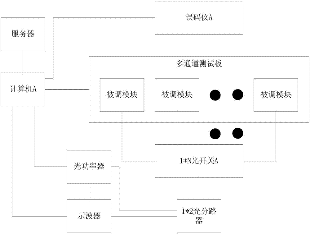
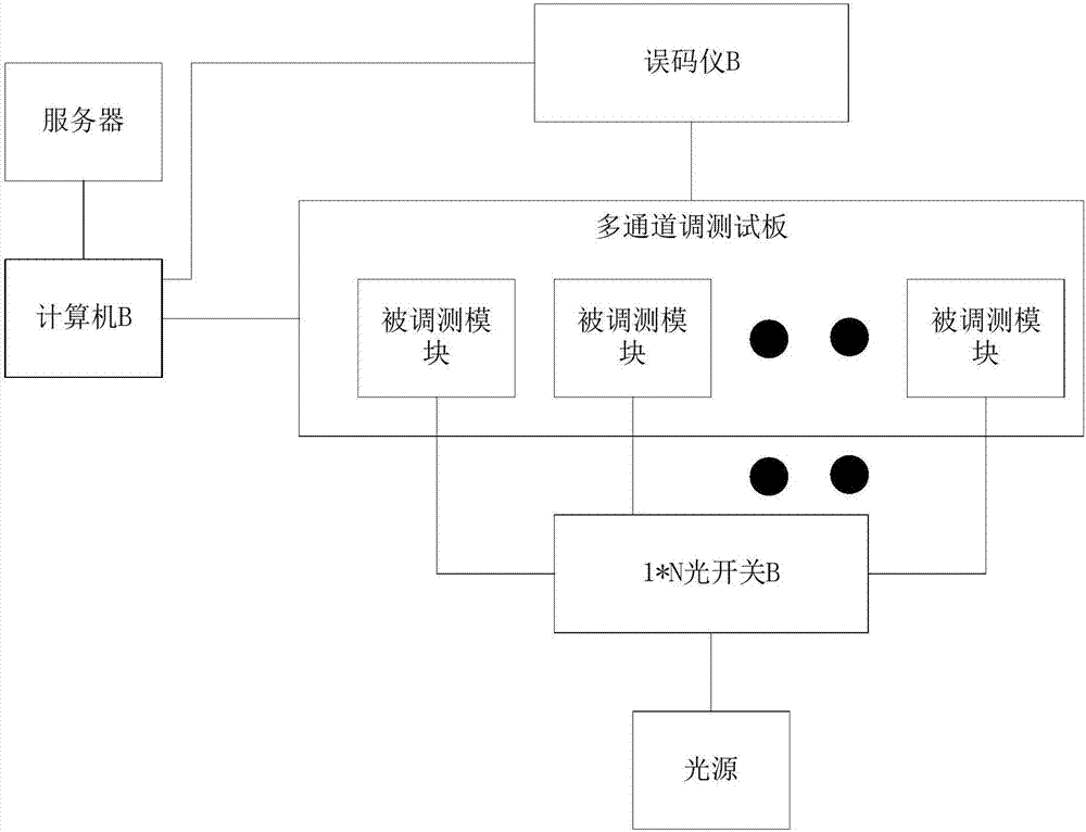
[0026] Such as figure 1 , figure 2 As shown, the optical module multi-channel automatic commissioning system disclosed in the present invention includes an optical transmitting module debugging device and an optical receiving module debugging device; the optical transmitting module debugging device includes a multi-channel debugging board, and the multi-channel debugging board is adapted to at least two The modulation module, the modulated module is connected to the optical switch A, the optical switch A is connected to the input end of the optical splitter, the two output ends of the optical splitter are respectively connected to the optical power meter and the oscilloscope, and both the optical power meter and the oscilloscope are connected to the computer A ,...


PUM


Abstract

The invention discloses an optical module multi-channel automatic debugging and testing system. The system comprises a light emitting module debugging device and a light receiving module debugging and testing device. The light emitting module debugging device comprises a multi-channel debugging board, the multi-channel debugging board is adapted to at least two debugged modules, the debugged modules are connected with an optical switch A, the optical switch A is connected with the input end of an optical splitter, two output ends of the optical splitter are respectively connected with an optical power meter and an oscilloscope, the optical power meter and the oscilloscope are both connected with a computer A, the computer A is connected with a server, the multi-channel debugging board and an error code tester A, and the error code tester A is connected with the multi-channel debugging board. The light receiving module debugging and testing device comprises a multi-channel debugging and testing board, the multi-channel debugging and testing board is adapted to at least two debugged and tested modules, the debugged and tested modules are connected with an optical switch B, the optical switch B is connected with a light source, the multi-channel debugging and testing board is connected with a computer B, and the computer B is connected with the server and an error code B. according to the invention, the debugging and testing efficiency of an optical module can be improved.

Description

technical field [0001] The invention relates to the field of optical communication, in particular to an optical module multi-channel automatic commissioning device. Background technique [0002] With the sharp increase in the demand for high-quality communication services, the demand for optical modules in optical communication systems has also increased sharply. [0003] The main items of optical module debugging include: [0004] 1. Write and verify product configuration information (chip configuration), manufacturer and protocol information; [0005] 2. TX end: transmit optical power, extinction ratio; [0006] 3. RX terminal: mainly setting the fast voltage point for the APD part; [0007] 4. Automatically calibrate the monitoring quantity of DDM module (including module temperature, supply voltage, Bias current, transmit optical power, receive optical power); [0008] System test parameters include: [0009] 1. Transmitted optical power, extinction ratio, eye diagr...

Claims


Application Information

Patent Timeline
IPC IPC(8): H04B10/073H04B10/40
CPCH04B10/0731H04B10/40
Inventor 夏兴胜
Owner CHENGDU GIGAC TECH CO LTD
Why Eureka
Try Eureka