Efficient crushing device for construction waste

A crushing device and construction waste technology, applied in the direction of dust removal, liquid separation agent, cleaning method and utensils, etc., can solve the problem of large land acquisition fees, construction funds for garbage removal and transportation, and insufficient recycling of iron materials , Waste of reusable resources and other issues, to achieve sustainable development, avoid wanton diffusion, and achieve the effect of recycling

Inactive Publication Date: 2017-12-12
李明超
View PDF0 Cites 24 Cited by
  • Summary
  • Abstract
  • Description
  • Claims
  • Application Information

AI Technical Summary

Problems solved by technology

However, the vast majority of construction waste is transported to the suburbs or villages by the construction unit without any treatment, and is stacked in the open air or landfilled, which consumes a lot of construction expenses such as land acquisition fees, garbage removal and transportation fees, and at the same time, during the process of clearing, transporting and stacking Problems such as the scattering of dust and flying dust and sand have caused serious environmental pollution.
[0003] However, the structure of the traditional construction waste crushing device is too complex, which has a negative impact on the comprehensive treatment of construction waste to a certain extent, and even forms an obstacle to the further development of the entire industry and the market; the current construction waste crushing device has insufficient crushing effect. The recyclable iron materials in construction waste are not fully recovered, which is likely to cause waste of reusable resources. In addition, in the process of garbage crushing, it is easy to generate a large amount of dust. The diffusion of dust directly affects the air quality of the environment. Can not meet the higher requirements of the modern construction industry

Method used


Image

  • Efficient crushing device for construction waste
  • Efficient crushing device for construction waste
  • Efficient crushing device for construction waste

Examples


Embodiment Construction

[0018] Below in conjunction with specific embodiment, the technical scheme of this patent is described in further detail:

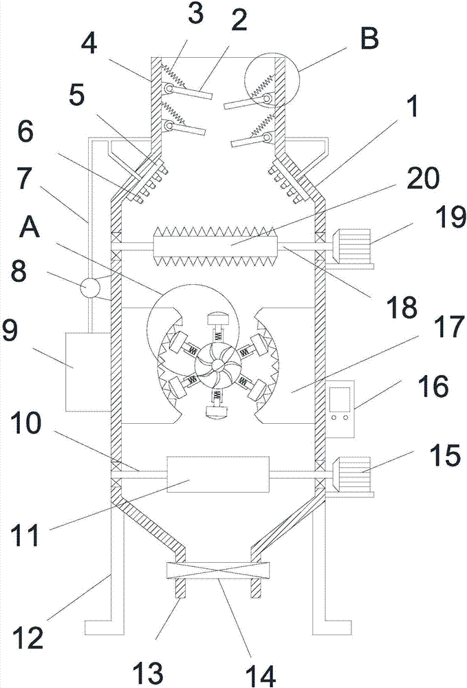
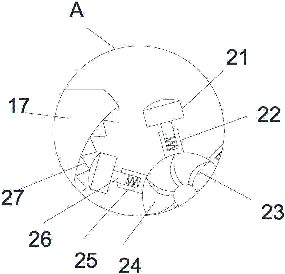
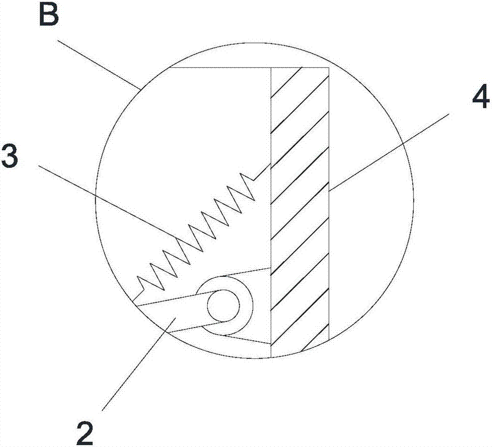
[0019] see Figure 1-3 , a high-efficiency crushing device for construction waste, including a crushing box 1, a feeding pipe 4 is arranged on the top of the crushing box 1, and a plurality of buffer plates 2 are arranged alternately on the inner wall of the feeding pipe 4, and one end of the buffer plate 2 is hinged On the inner wall of the feed pipe 4, the limit spring 3 is connected between the inner wall of the feed pipe 4 and the side of the buffer plate 2; A spray nozzle 6, a water tank 9 is arranged on the outer wall of the left side of the crushing box 1, and a catheter 7 is connected between the water tank 9 and the water collection tray 5, and a water pump 8 is installed on the catheter 7; the right side of the crushing box 1 A second motor 19 is arranged on the outer wall, and a second rotating shaft 18 is arranged horizontally in the crushing...


PUM


Abstract

The invention discloses a high-efficiency crushing device for construction waste, which comprises a crushing box, a feeding pipe is arranged on the top of the crushing box, a water collecting tray is arranged on the inner wall of the crushing box, and several nozzles are uniformly arranged on the surface of the water collecting tray, and the crushing box There is a water tank on the outer wall on the left side, and a catheter is connected between the water tank and the water collection tray, and a water pump is installed on the catheter; the left and right inner walls of the crushing box are symmetrically equipped with limiting extrusion plates, and the sliding device inside the sleeve There is a sliding shaft, a damping spring is arranged in the sleeve, and the crushing pressure head is in contact with the sawtooth; a control box is provided on the outer wall on the right side of the crushing box, and the control box is electrically connected with the electromagnet plate; The crushing efficiency is high and the crushing effect is sufficient; the buffer plate buffers and absorbs the garbage entering the crushing box, reduces the impact on the crushing roller, improves the stability of the device, reduces mechanical loss and failure rate, and avoids construction The concentrated falling of garbage leads to uneven crushing.

Description

technical field [0001] The invention relates to the technical field of construction waste processing machinery, in particular to a high-efficiency crushing device for construction waste. Background technique [0002] Construction waste refers to the dregs, spoils, waste materials, residual mud and other wastes generated during the construction, laying or demolition and repair of various buildings, structures, pipe networks, etc. by construction, construction units or individuals. At present, the amount of construction waste in my country has accounted for 30%-40% of the total amount of urban waste. Calculated on the basis of 500-600 tons / 10,000 square meters, by 2020, my country will add about 30 billion square meters of new construction area, and the newly generated construction waste will be a shocking number. However, the vast majority of construction waste is transported to the suburbs or villages by the construction unit without any treatment, and is piled in the open ...

Claims


Application Information

Patent Timeline
Patent Type & Authority Applications(China)
IPC IPC(8): B02C4/00B02C4/28B02C13/04B02C23/16B02C23/18B03C1/30B08B15/04B01D47/06
CPCB02C4/00B01D47/06B02C4/28B02C13/04B02C23/16B02C23/18B02C2201/06B03C1/30B08B15/04
Inventor 李明超
Owner 李明超
Why Eureka
Try Eureka