Sharpening assembly

A component and grinding wheel technology, which is applied to the parts of grinding machine tools, grinding machines, grinding drives, etc., can solve the problems of reduced tool life, unfavorable on-site installation, and reduced cutting quality, so as to prolong the service life and reduce the cost of equipment. Effect of cost and life extension

Pending Publication Date: 2017-12-12
NANTONG MUYE MACHINERY
View PDF7 Cites 1 Cited by
  • Summary
  • Abstract
  • Description
  • Claims
  • Application Information

AI Technical Summary

Problems solved by technology

[0002] The sharpening device of the CNC cutting machine in the past requires manual control and adjustment of how much the grinding wheel advances and how much the knife is sharpened. In the later stage, the amount of sharpening will not be enough, the knife will not be sharpened, and the blade of the knife will become blunt, which will reduce the cutting quality, and this operation will greatly reduce the life of the knife
[0003] In the later period, our company made some related improvements, such as the patent applied in the past, the application date is 2014.12.29, the patent number is CN201420848079.9, which discloses a knife sharpening device for a CNC cutting machine, including a fixed seat, a knife sharpening motor, a grinding wheel, Servo motor, no need for manual adjustment, accurate sharpening amount, can be sharpened at any time, which greatly improves the sharpening efficiency, but one device needs to use two sharpening motors, two servo motors, the equipment cost is high, and the volume is large, Not conducive to field installation

Method used


Image

  • Sharpening assembly
  • Sharpening assembly
  • Sharpening assembly

Examples


Embodiment Construction

[0023] specific implementation plan

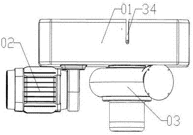
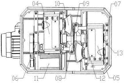
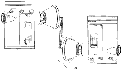
[0024] Refer to attached Figure 1-8 , a sharpening assembly, which includes a sharpening back plate 01, a sharpening mechanism 31, a driving mechanism 32, and an adjustment mechanism 33; the sharpening mechanism 31 includes a left housing 04, a right housing 05, a left housing 04, a right The casing 05 is arranged in the sharpening backboard 01, and is located at both ends of the sharpening backplane 01. The center of the left casing 04 and the right casing 05 is symmetrical, and the left casing 04 and the right casing 05 are respectively provided with a sharpening wheel 10 , a knife sharpening box 09 is arranged between the two knife sharpening wheels 10; knife grooves 34 are arranged on both sides of the knife sharpening back plate 01, and the knife grooves 34 are located at the same horizontal position as the knife sharpening box 09; the drive mechanism 32 includes a driving motor 02, fixedly installed on the sharpening backboard 01, ...


PUM


Abstract

The invention relates to a sharpening assembly. The sharpening assembly comprises a sharpening back plate, a sharpening mechanism, a driving mechanism and an adjusting mechanism. The sharpening mechanism comprises a left shell and a right shell, the left shell and the right shell are arranged in the sharpening back plate and correspondingly provided with sharpening grinding wheels, a sharpening cutter box is arranged between the two sharpening grinding wheels, sharpening grooves are formed in the two sides of the sharpening back plate, and the sharpening grooves are located in the same horizontal position with the sharpening cutter box. The driving mechanism comprises a driving motor, and the driving motor is in driving connection with the two sharpening grinding wheels to control the grinding wheels to rotate. The adjusting mechanism comprises a servo motor, and the servo motor is in driving connection with the left shell and the right shell to control the left shell and the right shell to slide horizontally. The sharpening assembly has the advantages that the design is simple and ingenious and convenient to use, manual adjusting is not needed, the sharpening amount can be precisely controlled, it is ensured that sharpening is also achieved during running of equipment, the sharpening efficiency is greatly improved, the equipment cost is reduced, the equipment size is reduced, and the installation is more convenient.

Description

technical field [0001] The invention relates to the field of cutting machines, in particular to a sharpening assembly. Background technique [0002] The sharpening device of the CNC cutting machine in the past requires manual control and adjustment of how much the grinding wheel advances and how much the knife is sharpened. In the later stage, the amount of sharpening will be insufficient, the knife will not be sharpened, and the blade of the knife will become blunt, which will reduce the cutting quality, and this operation will greatly reduce the life of the knife. [0003] In the later period, our company made some related improvements, such as the patent applied in the past, the application date is 2014.12.29, the patent number is CN201420848079.9, which discloses a knife sharpening device for a CNC cutting machine, including a fixed seat, a knife sharpening motor, a grinding wheel, Servo motor, no need for manual adjustment, accurate sharpening amount, can be sharpened ...

Claims


Application Information

Patent Timeline
Patent Type & Authority Applications(China)
IPC IPC(8): B24B3/36B24B27/00B24B47/12B24B47/20
CPCB24B3/36B24B27/0076B24B47/12B24B47/20
Inventor 缪小龙
Owner NANTONG MUYE MACHINERY
Why Eureka
Try Eureka