Integrated type electric turnover box and production method

An integrated, turnover box technology, applied in the direction of preventing mechanical damage, rigid containers, containers, etc., can solve the problems of reduced production and transportation safety performance, unfavorable product status maintenance, difference in turnover box specifications, etc., to improve stacking stability. stability, avoid the difference in structure and size, and achieve the effect of accurate product size

Pending Publication Date: 2017-12-12
SUZHOU YING CHUANG POWER TECH
View PDF6 Cites 2 Cited by
  • Summary
  • Abstract
  • Description
  • Claims
  • Application Information

AI Technical Summary

Problems solved by technology

The production process of the side plate and the bottom plate is controllable, and the connection process such as welding will cause the difference in the specification of the turnover box
In order to improve the utilization rate of space, the storage and transportation process of the turnover box is realized in the form of stacking the turnover box, and the specification difference of the turnover box will lead to the instability of the stacking state, which reduces the safety performance of production and transportation. Not conducive to the maintenance of product status

Method used


Image

  • Integrated type electric turnover box and production method
  • Integrated type electric turnover box and production method
  • Integrated type electric turnover box and production method

Examples


Embodiment Construction

[0041] The present invention will be further described below in conjunction with the accompanying drawings and specific embodiments.

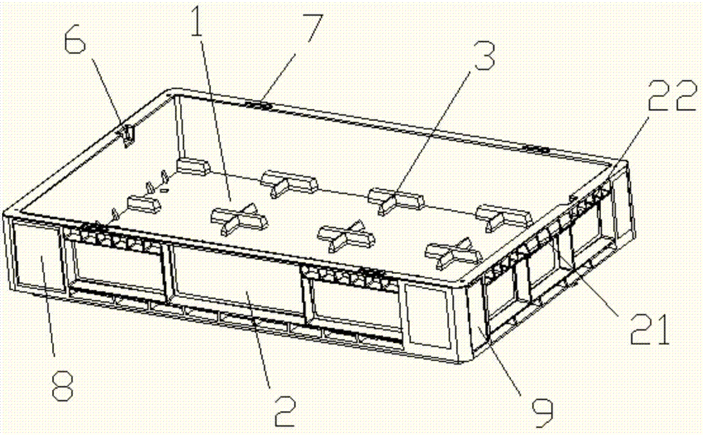
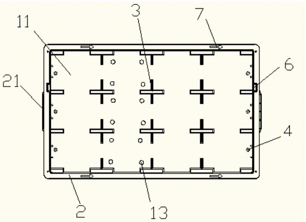
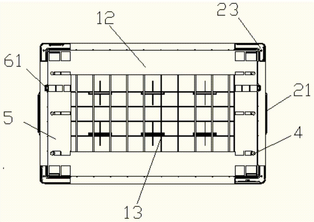
[0042] The turnover box is composed of a side plate 2 and a bottom plate 1 , and the side plate 2 is vertically connected to the upper surface 11 of the bottom plate 1 . This moment, this side plate 2 and base plate 1 surround and form the placement area for accommodating tools, and its structure is as follows: figure 1 shown. The forming method of the side plate 2 and the bottom plate 1 of this application adopts integral injection molding, which saves the connection process of the side plate 2 and the bottom plate 1. According to different customer needs, the change of the finished structure of the turnover box can be realized by changing the shape of the mold, and the improvement can be improved. Improve the production efficiency of the turnover box. And the overall injection molding method is made by model, which makes the product size mo...


PUM


Abstract

The invention discloses an integrated type electric turnover box and a production method applied to the electric field. The integrated type electric turnover box is characterized by structurally comprising a bottom plate and side plates, wherein the bottom plate comprises an upper surface and a lower surface; the side plates are perpendicularly arranged on the upper surface; the side plates are enclosed to form a placing region; and the bottom plate and the four side plates are injection-molded integrally. The integrated type electric turnover box is injection-molded integrally, so that a connecting process of the side plates and the bottom plate is reduced, production efficiency is improved and production cost is reduced. Changes of the structure of the turnover box finished product can be realized by changing a mould shape according to different customer requirements, so that production efficiency of the turnover box is improved. The turnover box is manufactured through a model, so that the product dimension is more precise, structural dimension difference, caused by the connecting process of the bottom plate and the side plates, of the turnover box finished product is avoided, structural consistency of the turnover boxes produced in batch is effectively improved, stacking effect of the turnover box is guaranteed, stacking stability is improved, and guarantee is provided for a follow-up operation process.

Description

technical field [0001] The invention relates to an integrated power turnover box applied in the electric power field and a production method thereof. Background technique [0002] With the wide application of power equipment, the demand for power tools is gradually increasing. The tool is manufactured by a special manufacturer, and then the tool is placed in the turnover box, thereby realizing a large amount of storage and safe transportation of the tool. The production process of the turnover box usually manufactures the side plate and the bottom plate separately, and then connects them through the welding process, and the production process efficiency is low. The production process of the side panels and the bottom panel is controllable, and the connection process such as welding will cause the difference in the specification of the turnover box. In order to improve the utilization rate of space, the storage and transportation process of the turnover box is realized in t...

Claims


Application Information

Patent Timeline
Patent Type & Authority Applications(China)
IPC IPC(8): B65D6/02B65D81/02B65D21/032B29C45/00B29B13/06
CPCB65D11/10B65D21/0204B65D81/02B29C45/00B29C2045/0096
Inventor 何锡斌杨金娥孟敏
Owner SUZHOU YING CHUANG POWER TECH
Why Eureka
Try Eureka