Supercharge Your Innovation With Domain-Expert AI Agents!

Mechanical type rope arranger

A kind of mechanical technology of rope arranging device, applied in the field of rope arranging device, can solve the problems of complex control process of rope arranging device, affecting work efficiency, and many fault points, etc., and achieves the effect of flexible adjustment, reasonable structure and few fault points

Pending Publication Date: 2017-12-12
SHANGHAI ZHENHUA HEAVY IND
View PDF5 Cites 2 Cited by
  • Summary
  • Abstract
  • Description
  • Claims
  • Application Information

AI Technical Summary

Problems solved by technology

[0003] The rope guides used on existing winches are usually electric or hydraulic rope guides, which use various encoders and program settings to achieve the position of the rope outlet of the rope guide and the exit position of the steel wire rope on the drum. position, but the control process of this kind of rope rower is complicated, the equipment is expensive, and there are many fault points, and problems often occur, resulting in the need to stop work and troubleshoot and eliminate faults, which greatly affects work efficiency

Method used


Image

  • Mechanical type rope arranger
  • Mechanical type rope arranger
  • Mechanical type rope arranger

Examples


Embodiment Construction

[0036] The technical solutions of the present invention will be further described below in conjunction with the accompanying drawings and embodiments.

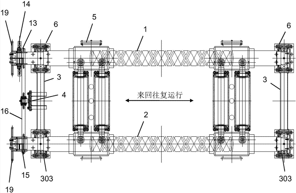
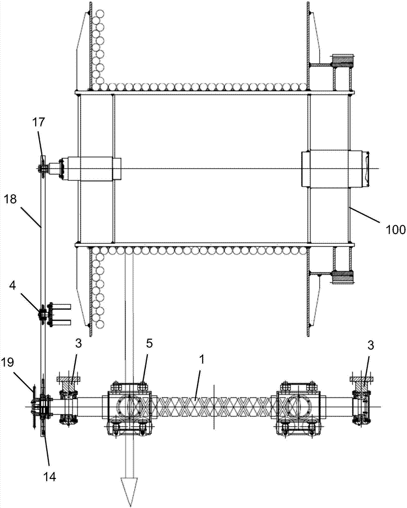
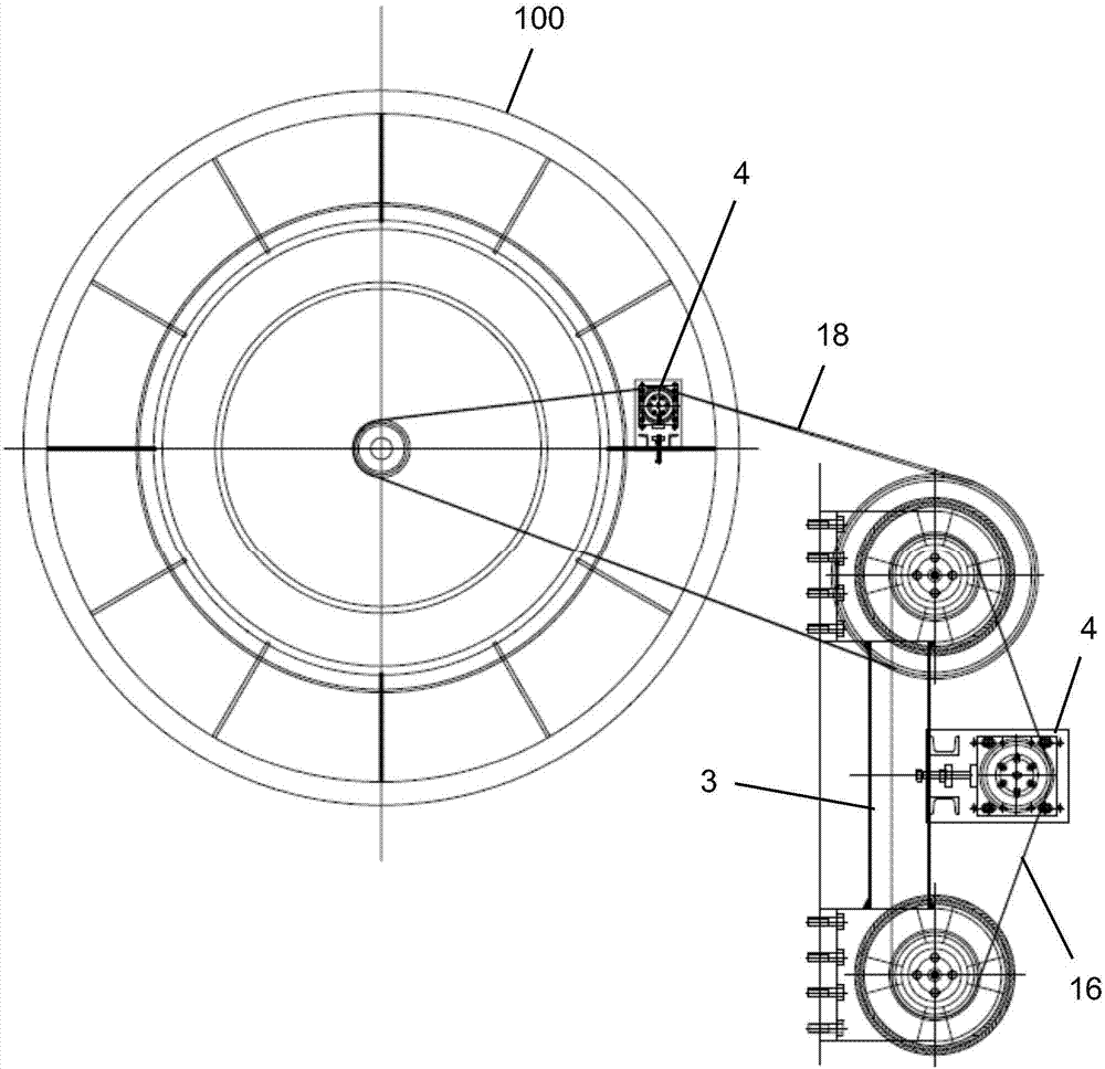
[0037] Please combine Figure 1 to Figure 9 As shown, a mechanical rope remover provided by the present invention is arranged on one side of the reel 100 and connected to the reel 100, including a first screw 1, a second screw 2, a frame 3. The tensioning assembly 4 and the carriage assembly 5 are arranged in parallel between the first screw 1 and the second screw 2, and are connected by the frame 3 on the left and right ends of the first screw 1 and the second screw 2, and slide The upper and lower ends of the frame assembly 5 are respectively sleeved on the first screw 1 and the second screw 2, so that the carriage assembly 5 can slide back and forth on the first screw 1 and the second screw 2, and the first screw 1 is arranged on one side of the reel 100 and connected with the reel 100.

[0038] Preferably, the frame 3 in...


PUM


Abstract

The invention discloses a mechanical type rope arranger. The mechanical type rope arranger is arranged at one side of a winding drum and connected with the winding drum. The mechanical type rope arranger comprises a first threaded rod, a second threaded rod, racks, tensioning assemblies and slide bracket assemblies. The first threaded rod is arranged to be parallel with the second threaded rod and connected with the second threaded rod through the racks. The two ends of the slide bracket assemblies are arranged on the first threaded rod and the second threaded rod in a sleeving manner correspondingly, so that the slide bracket assemblies move on the first threaded rod and the second threaded rod back and forth in a reciprocating and sliding manner. The first threaded rod is arranged at one side of the winding drum. The upper ends and the lower ends of the racks are each provided with a bearing seat. A first chain wheel and a driven chain wheel are arranged at one end of the first threaded rod, and a second chain wheel is arranged at one end of the second threaded rod. The second chain wheel is connected with the first chain wheel through a synchronous chain. A driving chain wheel is arranged at the portion of one end of the winding drum. The driving chain wheel is connected with the driven chain wheel through a driving chain. The synchronous chain and the driving chain are each provided with the corresponding tensioning assembly. By means of the mechanical type rope arranger, the design cost and the manufacturing cost are lowered; fault points are reduced; and practicability and economical efficiency of products are improved.

Description

technical field [0001] The invention relates to a rope puller on a positioning winch, more specifically, to a mechanical rope puller. Background technique [0002] The winch is a large-scale equipment widely used in marine engineering, electric power, mining, cement, steel, chemical industry, papermaking and other industries. The length of the wire rope wound on the winch is long (usually hundreds of meters to thousands of meters), and in The rope is continuously paid back and forth within the width of the reel (forming multi-layer winding). In order to arrange the steel wire rope on the reel neatly and orderly, the winch is equipped with a rope puller. The rope puller needs to ensure that the rope The position of the rope exit of the device is always completely synchronized with the position of the steel wire rope on the drum, and it can also reliably press the rope so that the steel wire rope cannot jump out of the groove, thereby prolonging the service life of the steel w...

Claims


Application Information

Patent Timeline
IPC IPC(8): B66D1/38
CPCB66D1/38B66D2700/0191
Inventor 周大乔丛海军王亚斌王硕锋杨杰魏辽国司翔
Owner SHANGHAI ZHENHUA HEAVY IND
Features
  • R&D
  • Intellectual Property
  • Life Sciences
  • Materials
  • Tech Scout
  • Unparalleled Data Quality
  • Higher Quality Content
  • 60% Fewer Hallucinations
Learn More