Closed loop current sensor

A current sensor and closed-loop technology, applied in the direction of only measuring current, voltage/current isolation, measuring current/voltage, etc., can solve the problems of large sensor size, high production cost, heavy weight, etc., and achieve small size, low production cost, light weight effect

Pending Publication Date: 2017-12-12
NING BO SINOMAGS ELECTRONICS TECH CO LTD
View PDF1 Cites 8 Cited by
  • Summary
  • Abstract
  • Description
  • Claims
  • Application Information

AI Technical Summary

Problems solved by technology

[0006] In view of this, an embodiment of the present invention provides a closed-loop current sensor to solve the problems of the existing closed-loop current sensor with large volume, heavy weight and high production cost

Method used


Image

  • Closed loop current sensor
  • Closed loop current sensor
  • Closed loop current sensor

Examples


Embodiment 1

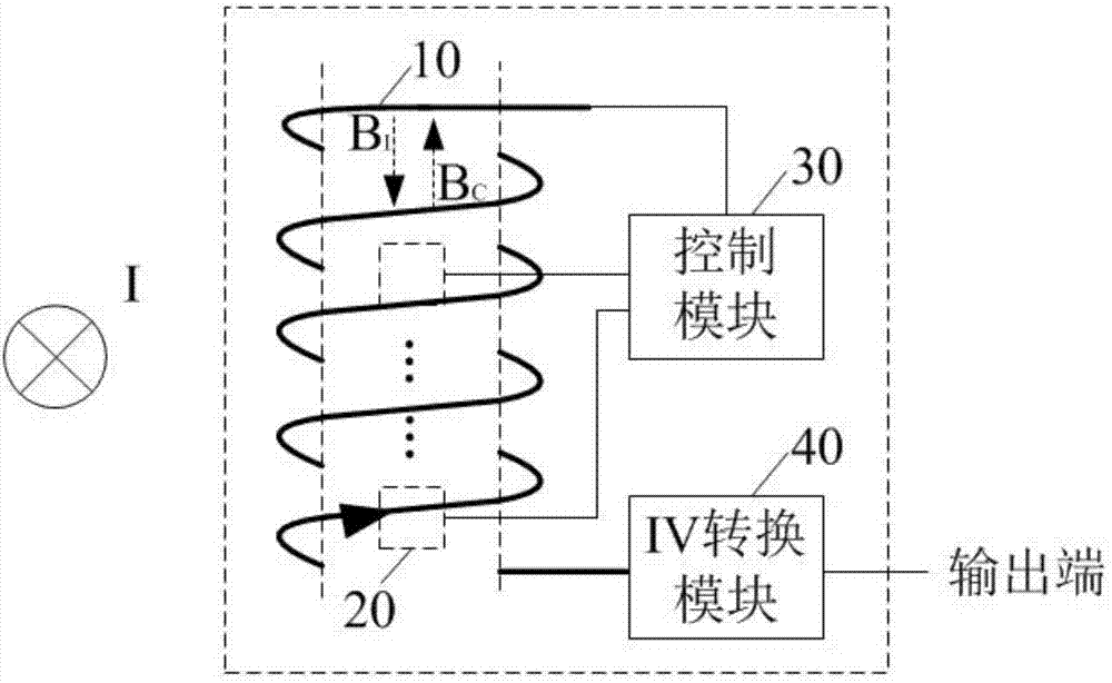
[0031] figure 2 A schematic diagram of a closed-loop current sensor according to an embodiment of the present invention is shown. Such as figure 2 As shown, the closed-loop current sensor includes at least one compensation coil 10 , at least one magnetic sensor chip 20 , a control module 30 and an IV conversion module 40 . figure 2 The "×" on the left side of the center indicates that the wire through which the current to be measured flows is perpendicular to the paper, and the current flows in the direction of penetrating the paper.

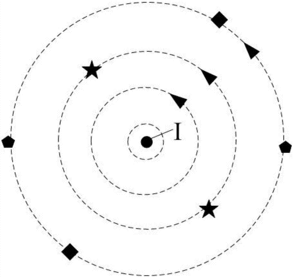
[0032] The compensation coil 10 is arranged at a predetermined position of the wire through which the current to be measured flows, and is used to generate a compensation magnetic field opposite to the magnetic field of the current to be measured. The "predetermined position" refers to the distance and orientation relative to the wire through which the current to be measured flows, image 3 and Figure 4 Several scenarios of predetermined...

Embodiment 2

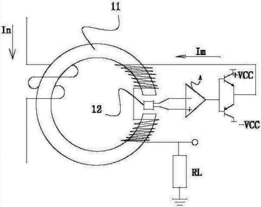
[0040] Figure 5 A schematic diagram of another closed-loop current sensor according to an embodiment of the present invention is shown. Such as Figure 5 As shown, the difference from Embodiment 1 is that the closed-loop current sensor includes at least two compensation coils 11 and 12 , two magnetic sensor chips 21 and 22 , a control module 30 , and an IV conversion module 40 .

[0041] The magnetic sensor chip 21 is arranged in the lumen of the compensation coil 11 , and the magnetic sensor chip 22 is arranged in the lumen of the compensation coil 12 . The wire through which the current to be measured flows is arranged between the two compensation coils 21 and 22 .

[0042] Figure 5 The "×" in means that the current to be measured flows through the wire perpendicular to the paper, and the current flows in the direction of penetrating the paper, B I1 and B I2 Indicates the magnetic field of the current to be measured, B C1 and B C2 Indicates the magnetic field of the...


PUM


Abstract

The invention discloses a closed loop current sensor which comprises at least one compensation coil, at least one magnetic sensing chip, a control module and an IV conversion module, wherein the compensation coils are arranged at preset positions on a lead wire where to-be-detected current flows; each magnetic sensing chip is arranged in a tube cavity of one compensation coil, and is used for measuring intensities of a magnetic field of the to-be-detected current and a superposed magnetic field of the compensation coil; the control module is used for outputting current at preset magnitude according to output signals of the magnetic sensing chips; an input end of the control module is connected with output ends of the magnetic sensing chips, and an output end of the control module is connected with one end of each compensation coil; an input end of the IV conversion module is connected with the other end of each compensation coil, and an output end of the IV conversion module is used as an output end of the closed loop current sensor. As the magnetic field intensities in the tube cavities of the compensation coils are relatively uniform, the magnetic sensing chips of the closed loop current sensor can accurately measure the intensity of the superposed magnetic field in the absence of a magnetic core. The closed loop current sensor without the magnetic core is relatively small in volume, relatively light in weight and low in manufacturing cost.

Description

technical field [0001] The invention relates to the technical field of current sensors, in particular to a closed-loop current sensor. Background technique [0002] Current sensors are widely used in new energy, intelligent transportation, industrial control, smart home appliances, and smart grids. Commonly used current sensors are divided into two categories: open-loop and closed-loop. The open-loop current sensor is to set a magnetic core with an air gap around the wire to be tested. The magnetic sensing unit is located in the air gap. Due to the law of electromagnetic induction, the magnetic core generates an induced potential, and the magnetic sensing unit can measure the magnetic core gas. The magnetic field at the gap, the back end can calculate the magnitude of the measured current according to the output signal of the magnetic sensing unit. The working mode of the open-loop current sensor is to directly measure the magnetic field. Therefore, under the action of a l...

Claims


Application Information

Patent Timeline
IPC IPC(8): G01R15/20G01R19/00
CPCG01R15/205G01R15/207G01R19/0092
Inventor 王建国朱海华白建民于方艳
Owner NING BO SINOMAGS ELECTRONICS TECH CO LTD
Why Eureka
Try Eureka