MBUS circuit for centralized meter reading system

A technology of centralized meter reading and circuits, applied in signal transmission systems, electrical signal transmission systems, instruments, etc., can solve the problems of unfavorable electronic meter market promotion and application, unstable work, and many components, so as to reduce the difficulty of control and The cost of the equipment, the circuit is simple and reliable, and the effect of fewer components

Active Publication Date: 2017-12-12
HENAN ZHUOZHENG ELECTRONICS TECH CO LTD
View PDF6 Cites 4 Cited by
  • Summary
  • Abstract
  • Description
  • Claims
  • Application Information

AI Technical Summary

Problems solved by technology

[0002] With the growth of the national economy, all kinds of civilian meters have been converted from the original mechanical metering and manual on-site meter reading to the new method of electronic metering and automatic meter reading. It can read back the values ​​of all meters in an area in a short time, and form a report that is easy for people to identify and read, which saves a lot of manpower and time; among them, the transfer collector and electronic meter equipment Inter-communication has become an important part of the entire centralized meter reading system. For this reason, different experts and scholars at home and abroad have proposed different communication methods. Among them, the MBUS bus communication method (Meter BUS, instrument bus) is very convenient to use. During work, through The conversion between the single-chip processor signal of the transfer collector and the MBUS instrument bus signal provides the basis for the centralized meter reading system to realize the value reading of the meter; however, in the existing technology, the peripherals matching the MBUS bus circuit The components and the MBUS bus are integrated during manufacture, which has the disadvantages of high cost, few functions, unstable operation, and many components, which is not conducive to the market promotion and application of electronic meters

Method used


Image

  • MBUS circuit for centralized meter reading system
  • MBUS circuit for centralized meter reading system
  • MBUS circuit for centralized meter reading system

Examples


Embodiment Construction

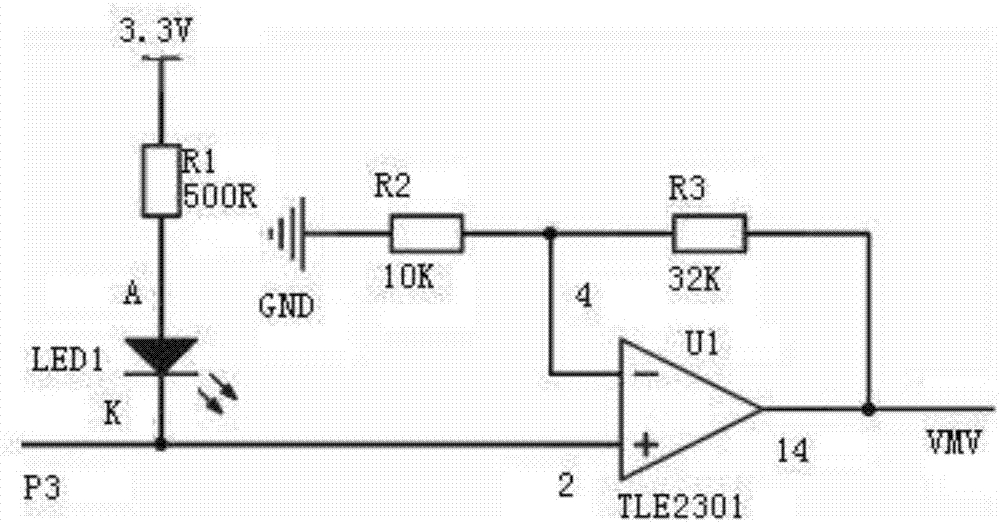
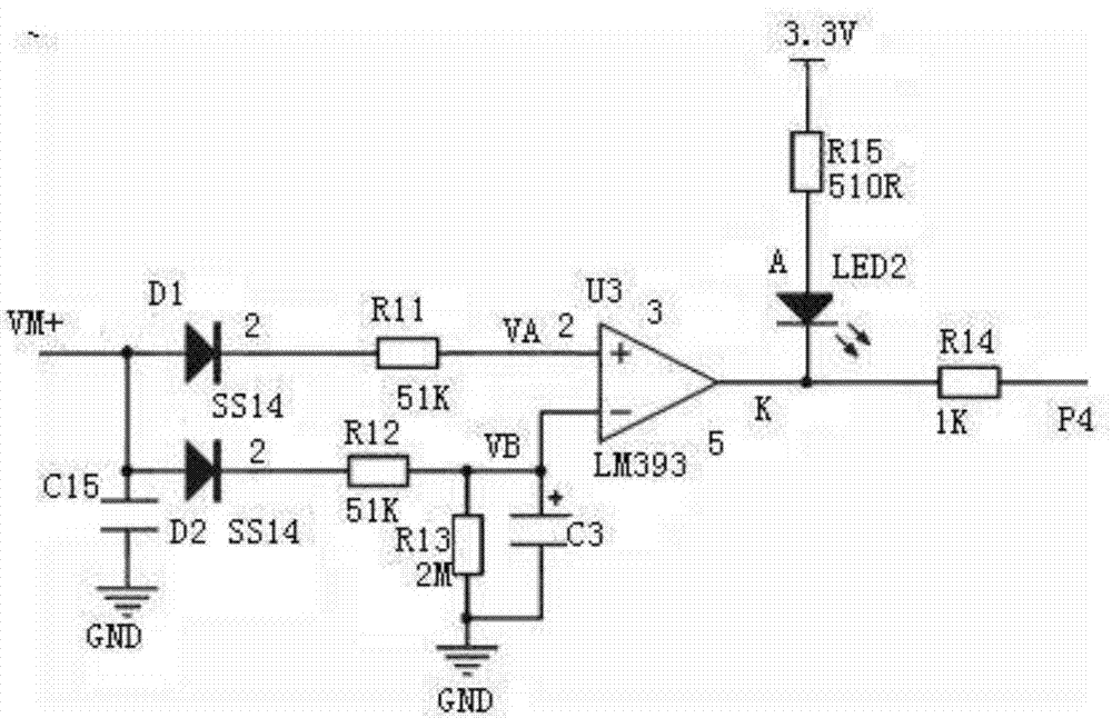
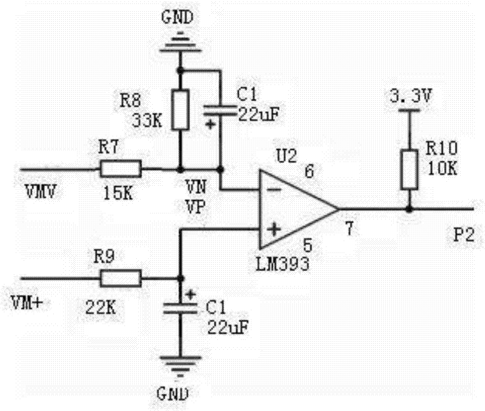
[0019] figure 1 , 2, 3, 4, 5, and 6, the data signal sending sub-circuit is composed of resistors R1, R2, R3, light-emitting diode LED1 and integrated chip U1, which are connected by wires. The integrated chip U1 is a power operational amplifier, the model is TLE2301 , There are three resistors, one end of the first resistor R1 is connected to the anode of the light-emitting diode LED1, one end of the second resistor R2 is connected to the third resistor R3, and the square reverse input terminal 4 of the power operational amplifier U1 is connected, and the third resistor The other end of R3 is connected to pin 14 of the output terminal of U1 of the power operational amplifier, and the negative pole of the light-emitting diode LED1 is connected to pin 2 of the positive input terminal of the power operational amplifier U1. The MBUS data receiving sub-circuit is composed of resistors R11, R12, R13, R15, R14, non-polar capacitor C15, polar capacitor C3, light-emitting diode LED2,...


PUM


Abstract

The invention relates to a MBUS circuit for a centralized meter reading system. The MBUS circuit is composed of a data signal sending sub-circuit, a MBUS data receiving sub-circuit, a MBUS load overload detection sub-circuit, a MBUS power control sub-circuit and a MBUS output sub-circuit which are connected with each other through wires and are arranged on a circuit board. According to the invention, each circuit has a clear function and is easily realized; the simple data signal sending sub-circuit, MBUS data receiving sub-circuit, MBUS load overload detection sub-circuit, MBUS power control sub-circuit and MBUS output sub-circuit are adopted for realizing a switching function between a single chip processor signal and a MBUS bus signal in a transferring collector; the MBUS circuit has the advantages of few elements, simple circuit, high stability, high safety, and the like; in such a manner, the MBUS circuit is easy to popularize and is easily marketed; the circuit is simple and reliable; the control difficulty and the equipment cost are reduced; the MBUS circuit has a wide application prospect.

Description

technical field [0001] The invention relates to the application field of instrument electronic technology, in particular to an MBUS circuit used in a centralized meter reading system. Background technique [0002] With the growth of the national economy, all kinds of civilian meters have been converted from the original mechanical metering and manual on-site meter reading to the new method of electronic metering and automatic meter reading. In the operation, one person cooperates with one computer. It can read back the values ​​of all meters in an area in a short time, and form a report that is easy for people to identify and read, which saves a lot of manpower and time; among them, the transfer collector and electronic meter equipment Inter-communication has become an important part of the entire centralized meter reading system. For this reason, different experts and scholars at home and abroad have proposed different communication methods. Among them, the MBUS bus communi...

Claims


Application Information

Patent Timeline
Patent Type & Authority Applications(China)
IPC IPC(8): G08C17/02G08C19/00
CPCG08C17/02G08C19/00
Inventor 谢小品李信波刘硕闫增伟
Owner HENAN ZHUOZHENG ELECTRONICS TECH CO LTD
Why Eureka
Try Eureka