Single-oscillating-arm leftward and rightward co-bending type numerical control pipe bending machine

A pipe bending machine and pipe bending technology, which is applied in the field of single swing arm left and right co-bending CNC pipe benders, can solve the problems of affecting the quality of the bending pipe, unstable pipe bending devices, and inability to configure the swing arm clamping mechanism, etc. Improve the stability of product manufacturing accuracy, ensure parallelism, and ensure the effect of transmission stability

Active Publication Date: 2017-12-15
浙江和良智能装备有限公司
View PDF9 Cites 14 Cited by
  • Summary
  • Abstract
  • Description
  • Claims
  • Application Information

AI Technical Summary

Problems solved by technology

Although it can achieve left and right co-bending, in order to avoid the interference of the rotating gear on the bending process, the two centering shafts are required to be far away from the rotating gear in height, and the swing arm and the clamping mechanism on the swing arm cannot be configured. , it is easy to cause the instability of the whole pipe bending device and affect the quality of the pipe bending

Method used


Image

  • Single-oscillating-arm leftward and rightward co-bending type numerical control pipe bending machine
  • Single-oscillating-arm leftward and rightward co-bending type numerical control pipe bending machine
  • Single-oscillating-arm leftward and rightward co-bending type numerical control pipe bending machine

Examples


Embodiment 1

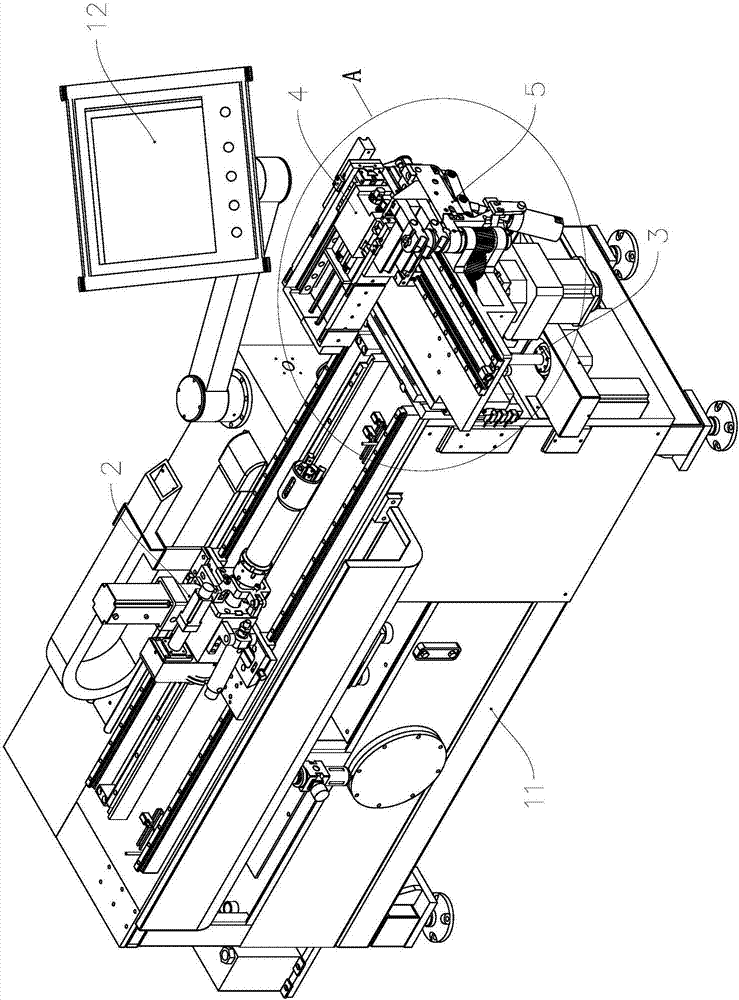
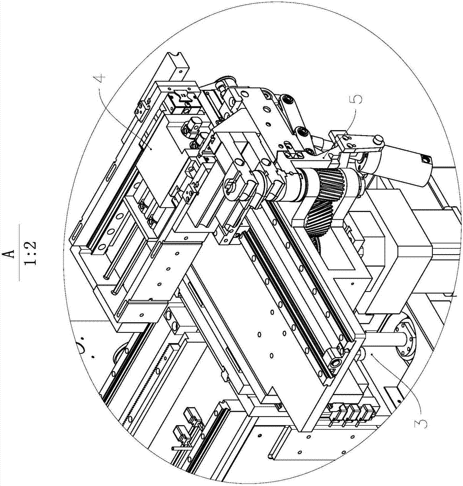
[0045] see figure 1 and figure 2 , the CNC pipe bending machine 1 includes a frame 11, a control unit, and a pipe bending device and a feeding trolley 2 installed on the frame 11 and controlled by the control unit; wherein, the pipe bending device includes a switching unit 3 and a mold guiding unit 4 And nose 5.

[0046] In this embodiment, the control unit includes a processor, a memory, and a touch screen 12. The processor receives input instructions from the operator through the touch screen 12, and at the same time controls the action of the pipe bending device and the feeding trolley 2 by executing the corresponding computer program stored in the memory. Perform pipe bends, switchovers, and more.

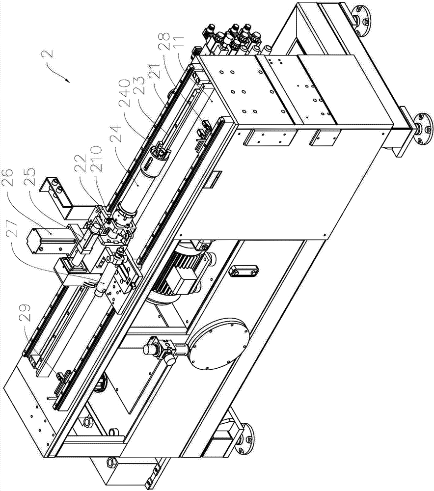
[0047] see image 3 , the feeding trolley 2 includes a feeding rail 21 fixed on the frame 11, a feeding slide 22 slidably installed on the feeding rail 21 through a slider 210, arranged and fixed on the frame 11 along a direction parallel to the feeding rail 21 The feeding...

Embodiment 2

[0094] As a description of Embodiment 2 of the present invention, only the differences from Embodiment 1 above will be described below, that is, only the structure of the clamping mold assembly will be described.

[0095] see Figure 17 and Figure 18 , by setting a pin hole 5170 on the side wall plate of the installation 50, in this embodiment, the adjustment locking mechanism also includes a locking pin 961 and a locking screw 962, and the outer port of the pin hole 5170 is provided with a locking screw 962 Matching threads, the inner end surface of the anti-loosening pin 961 is formed with an arc-shaped extrusion surface 9610 that matches the side wall surface of the mounting shaft portion 761 of the eccentric shaft 76, and the arc-shaped extrusion of the anti-loosening pin 961 is made by the locking screw 962. The pressing surface 9610 presses the side wall surface of the mounting shaft portion 761 to form a friction fit surface to assist in locking the rotation angle pos...

Embodiment 3

[0097] As an explanation of Embodiment 3 of the present invention, only the differences from Embodiment 1 above will be described below.

[0098] see Figure 19 and Figure 20 , multiple rings of locking holes uniformly arranged in the radial direction (only two rings are shown in the figure) can be provided on the fixed hole plate 953 , and each ring of locking holes is evenly arranged along the circumference of the hole plate. And in the gear gap adjustment hole plate 952, a multi-turn locking hole with the same number of turns and equal hole spacing in the radial direction is set (only two turns are shown in the figure), but there is a difference in the center angle of the interval between two adjacent turns, so that it can be The purpose of adjusting the rotation angle is achieved by aligning the locking holes at different radial positions.


PUM


Abstract

The invention relates to a single-oscillating-arm leftward and rightward co-bending type numerical control pipe bending machine and belongs to the technical field of pipe processing. The numerical control pipe bending machine comprises a machine frame, a control unit, a feeding trolley, a machine head, a mold guide unit and a switching unit, wherein the feeding trolley, the machine head, the mold guide unit and the switching unit are installed on the machine frame and controlled by the control unit; the machine head comprises a clamping mold, a round mold, an oscillating arm and a pipe bending motor, the oscillating arm shares the same drive spindle with the round mold, and the pipe bending motor is used for driving the round mold and the oscillating arm to rotate to bend a pipe and to rotate at the leftward pipe bending position or the rightward pipe bending position in a switching mode; and the switching unit is controlled by the control unit to drive the machine head to move transversely or vertically perpendicular to the axial direction of the pipe to be bent relative to the machine frame so that the machine head can be driven to switch between the leftward pipe bending position and the rightward pipe bending position. By means of the single-oscillating-arm leftward and rightward co-bending type numerical control pipe bending machine, leftward and rightward co-bending can be achieved based on the single oscillating arm, the pipe bending quality can be effectively improved, and the numerical control pipe bending machine can be widely applied to the fields of air conditioners, aviation and the like.

Description

technical field [0001] The invention relates to pipe material processing equipment, in particular to a single swing arm left and right co-bending type numerically controlled pipe bender. Background technique [0002] CNC pipe bending machines are widely used in air conditioners, automobiles, ships, aerospace and other industrial fields. The circular die used to control the radius of the pipe bending, the swing arm, the clamping die installed on the swing arm and used to clamp the pipe together with the circular die, and the circular die and the swing arm are driven to rotate around the rotation axis of the driving spindle to bend the pipe Tube bending motor for tube action. According to the different bending directions, it can be divided into left-bend type pipe bender, right-bend type pipe bender and left-right bend type pipe bender. [0003] The patent document with the publication number CN101817038A discloses a bending mechanism for building a left and right co-bending...

Claims


Application Information

Patent Timeline
Patent Type & Authority Applications(China)
IPC IPC(8): B21D7/00B21D7/12B21D7/16
CPCB21D7/00B21D7/12B21D7/16
Inventor 斯文尼尔·帕特里克·路易斯·雅克赵俊强李良有张良蔡前龙
Owner 浙江和良智能装备有限公司
Why Eureka
Try Eureka