
Coal conveyer emergency braking device and method

A technology for emergency braking and coal conveyors, which is applied in the direction of conveyor control devices, transportation and packaging, and conveyor objects. It can solve problems such as uneven force on the belt, deviation, and unfavorable emergency treatment, so as to avoid damage to equipment. , Fast and accurate positioning, easy to promote and use

Active Publication Date: 2017-12-15
XIAN UNIV OF SCI & TECH +1
View PDF7 Cites 0 Cited by
  • Summary
  • Abstract
  • Description
  • Claims
  • Application Information

AI Technical Summary

Problems solved by technology

In coal mine transportation, the belt conveyor generally needs to carry out long-distance, long working hours and heavy transportation work. Due to problems such as uneven force on the belt, offset of coal falling position, and large transportation inclination angle during use, the belt may slip. , deviation, broken belt, etc.
When the belt suddenly breaks due to overload, aging and other quality problems and improper operation, the tight belt will slide down quickly due to the break, and even fly out to hit the staff, and a large number of scattered coals will also hit the staff and workers. equipment, threatening the safety of personnel and damaging nearby equipment and facilities, causing huge economic losses
At present, the technologies that have been proposed are basically alarm devices for belt breakage, and the monitoring range is too wide to accurately determine the specific breakage point of the belt, which is not conducive to emergency treatment after breakage
Moreover, most of the relevant technologies only have an alarm function, and there is no protection function for emergency treatment of broken belts.

Method used


Image

  • Coal conveyer emergency braking device and method
  • Coal conveyer emergency braking device and method
  • Coal conveyer emergency braking device and method

Examples


Embodiment Construction

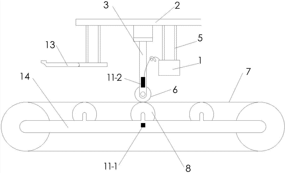
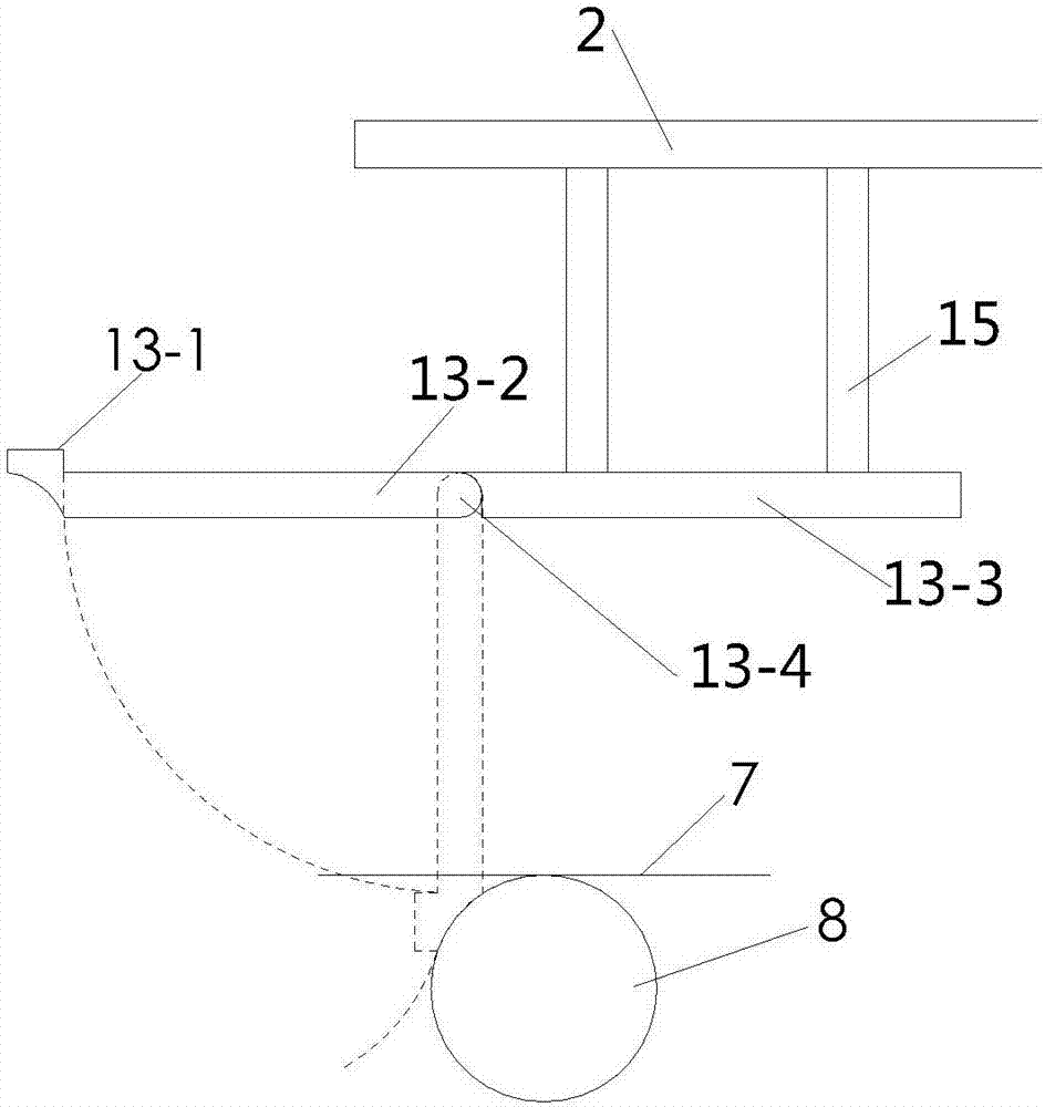
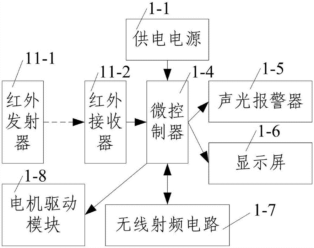
[0039] Such as Figure 1 to Figure 3 As shown, the emergency braking device of the coal transporter according to the present invention includes a remote console of the coal transporter and a plurality of emergency braking devices that communicate wirelessly with the remote console of the coal transporter, and the emergency braking device It includes a bracket 2 arranged above the coal conveyor, a brake mechanism mounted on the bracket 2 and cooperating with the auxiliary roller 8, an infrared detector for detecting the breakage of the belt 7 of the coal conveyor, and a brake mechanism for controlling the operation of the brake mechanism. The control box 1, the brake mechanism includes a vertical bar 3 fixed on the bracket 2 at one end, an electric pulley 6 that is rotatably mounted on the other end of the vertical bar 3 and in contact with the coal conveyor belt 7, and is used to press the coal conveyor The mechanical arm 13 of the belt 7, the infrared detector is composed of ...


PUM


Abstract

The invention discloses a coal conveyer emergency braking device and method. The coal conveyer emergency braking device comprises a coal conveyer remote console and a plurality of emergency braking devices. Each emergency braking device comprises a support, a braking mechanism, an infrared detector and a control box, wherein the braking mechanism is matched with auxiliary rollers. Each braking mechanism comprises a vertical rod, an electric pulley and a mechanical arm. One end of each vertical rod is fixed to the corresponding support, each electric pulley is installed at the other end of the corresponding vertical rod in a rotating mode and makes contact with a coal conveyer belt, and each mechanical arm is used for pressing the coal conveyer belt. Each infrared detector comprises an infrared emitter and an infrared receiver. The coal conveyer emergency braking method comprises the steps that firstly, the running state of a coal conveyer is monitored; secondly, whether the coal conveyer belt is broken or not is judged; thirdly, an audible and visual alarm is given, and emergency braking of the coal conveyer is conducted; and fourthly, the coal conveyer is braked. According to the coal conveyer emergency braking device and method, the breakage position of the belt is detected through the infrared detectors, and positioning is accurate; and the mechanical arms and the auxiliary rollers are matched to press and clamp the coal conveyer belt, so that emergency braking of the coal conveyer is achieved.

Description

technical field [0001] The invention belongs to the technical field of braking of a coal transporter, and in particular relates to an emergency braking device and method for a coal transporter. Background technique [0002] An important link in coal mine production is the coal mine transportation system. At present, the coal mine transportation system mainly adopts belt transportation. In coal mine transportation, the belt conveyor generally needs to carry out long-distance, long working hours and heavy transportation work. Due to problems such as uneven force on the belt, offset of coal falling position, and large transportation inclination angle during use, the belt may slip. , deviation, broken belt, etc. When the belt suddenly breaks due to overload, aging and other quality problems and improper operation, the tight belt will slide down quickly due to the break, and even fly out to hit the staff, and a large number of scattered coals will also hit the staff and workers....

Claims


Application Information

Patent Timeline
IPC IPC(8): B65G43/02
CPCB65G43/02
Inventor 郑学召李诚康金永飞费金彪邓军张铎李新卫杜瑞林
Owner XIAN UNIV OF SCI & TECH
Learn More