
Automatic element placing machine

A component and component technology, applied in the field of automatic component placement machines, can solve the problems of component drop, low component placement, and reduced production efficiency, and achieve the effects of neat component placement, novel structure, and ingenious design

Active Publication Date: 2017-12-15
嘉善梦溪服饰辅料厂(普通合伙)
View PDF10 Cites 1 Cited by
  • Summary
  • Abstract
  • Description
  • Claims
  • Application Information

AI Technical Summary

Problems solved by technology

[0003] 1. The traditional component placement machine has a complex structure, inconvenient operation, and low degree of automation integration, which can no longer meet the development needs of today's society;
[0004] 2. The traditional component placement mechanism often requires at least two operators to operate, which greatly reduces production efficiency and wastes human resources;
[0005] 3. The traditional component placement mechanism is prone to component drop during the component discharge and grabbing process, and the traditional component placement mechanism has low component placement

Method used


Image

  • Automatic element placing machine
  • Automatic element placing machine
  • Automatic element placing machine

Examples


Embodiment Construction

[0025] In order to make the technical means, creative features, goals and effects achieved by the present invention easy to understand, the present invention will be further elaborated below in conjunction with illustrations and specific embodiments.

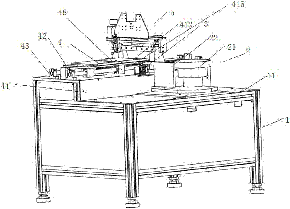
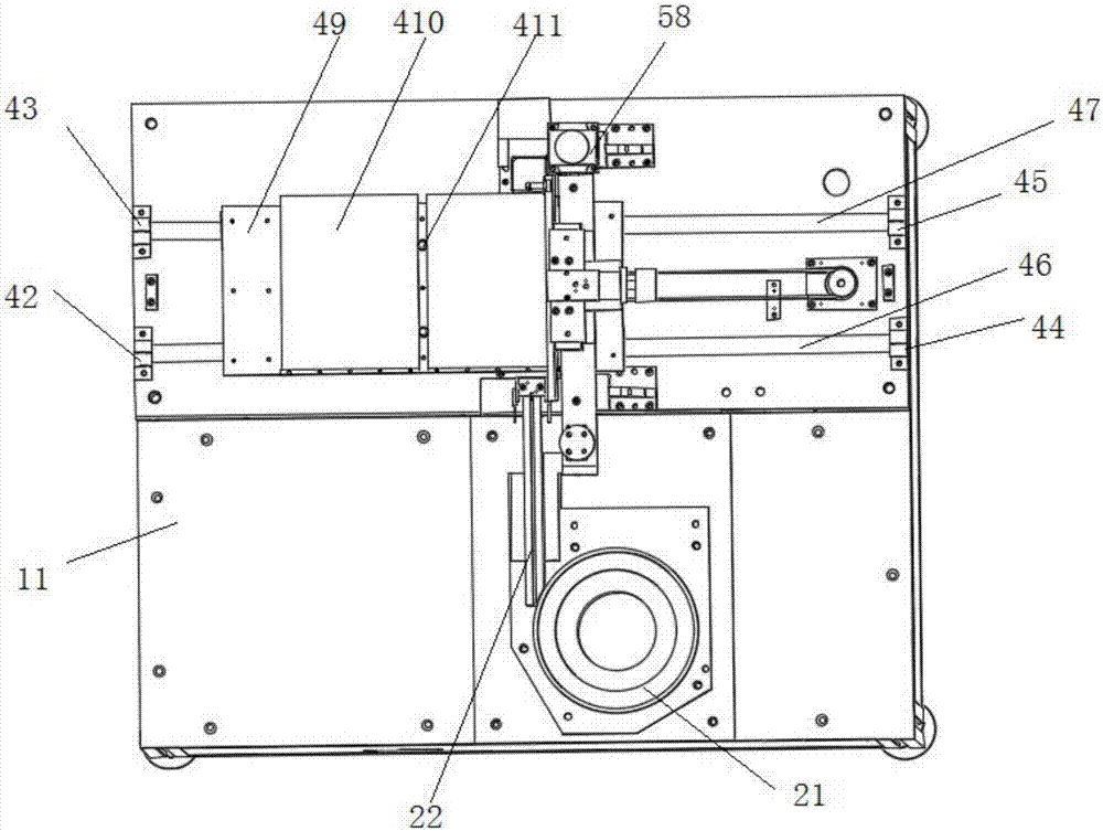
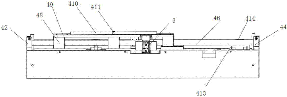
[0026] like Figure 1 to Figure 4 As shown, an automatic component placement machine proposed by the present invention includes a frame 1 and a work panel 11 arranged on the upper end of the frame 1, and the surface of the work panel 11 is also fixed with a component discharge assembly 2, a component top Lifting component 3, component placing component 4 and component grabbing component 5, the component discharging component 2 includes a vibrating feeding tray 21, and the discharge port end of the vibrating feeding tray 21 is connected with a discharging guide rail 22, the discharging The guide rail 22 is tangent to the vibrating feeding tray 21, and the component jacking assembly 3 is provided under the end of the discharge gui...


PUM


Abstract

The invention provides an automatic element placing machine comprising a rack and a work face plate arranged at the upper end of the rack. An element discharging assembly, an element jacking assembly, an element storing assembly and an element grabbing assembly are further fixed to the surface of the work face plate. The element discharging assembly comprises a vibrating feeding disc. The discharging outlet end of the vibrating feeding disc is connected with a discharging guide rail. The discharging guide rail is tangent to the vibrating feeding disc. The element jacking assembly is arranged below the tail end of the discharging guide rail and comprises two lifting air cylinders and a lifting plate connected to the top ends of piston rods of the lifting air cylinders.

Description

technical field [0001] The invention relates to the field of automation equipment, in particular to an automatic component placing machine. Background technique [0002] In the field of automation equipment, there are many kinds of processing equipment. Among them, the feeding and grabbing of components is one of the commonly used equipment, which is used to discharge and arrange components neatly. However, the traditional component placement machine has the following defects: [0003] 1. The traditional component placement machine has a complex structure, inconvenient operation, and low degree of automation integration, which can no longer meet the development needs of today's society; [0004] 2. The traditional component placement mechanism often requires at least two operators to operate, which greatly reduces production efficiency and wastes human resources; [0005] 3. The traditional component placement mechanism tends to drop the components during the component disc...

Claims


Application Information

Patent Timeline
Patent Type & Authority Applications(China)
IPC IPC(8): B65G47/26B65G47/14B65G47/92B65B35/38B65B35/34
CPCB65B35/34B65B35/38B65G47/1421B65G47/26B65G47/92B65G2201/02
Inventor 沈永强
Owner 嘉善梦溪服饰辅料厂(普通合伙)
Learn More