
Rapid magnetic separation sewage treatment system

A sewage treatment system and magnetic separation technology, applied in water/sewage treatment, magnetic field/electric field water/sewage treatment, adsorption water/sewage treatment, etc. Low efficiency and other problems, to achieve the effect of convenient use, conducive to recycling, and increase the effect of magnetic separation

Inactive Publication Date: 2017-12-15
绵阳西真科技有限公司
View PDF4 Cites 2 Cited by
  • Summary
  • Abstract
  • Description
  • Claims
  • Application Information

AI Technical Summary

Problems solved by technology

[0005] The purpose of the present invention is to overcome the deficiencies of the prior art and provide a fast magnetic separation sewage treatment system. The present invention is provided with a plate-type magnetic separation device, which can absorb and intercept sludge flocs containing magnetic powder, thereby It achieves magnetic separation and filtration, avoiding the problems of high moisture content, large amount of sludge and low magnetic recovery efficiency of the traditional sedimentation tank to filter sludge. The plate type magnetic separation device cooperates with the two-stage magnetic separation device to realize the multi-stage separation of magnetic sludge. Magnetic separation increases the effect of magnetic separation and is beneficial to the recycling and reuse of magnetic powder. The sludge after multi-stage magnetic separation can be directly transported out through the sludge treatment equipment without concentration

Method used


Image

  • Rapid magnetic separation sewage treatment system
  • Rapid magnetic separation sewage treatment system
  • Rapid magnetic separation sewage treatment system

Examples


Embodiment

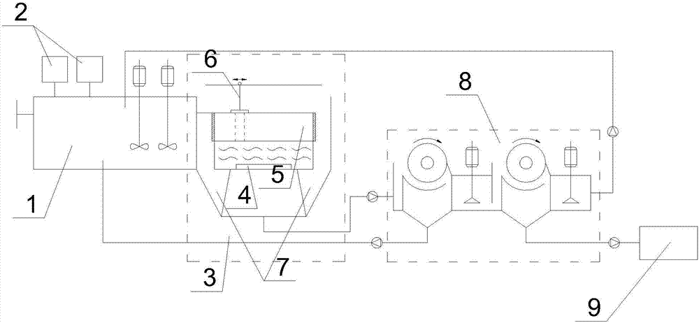
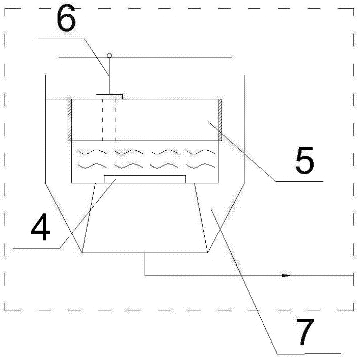
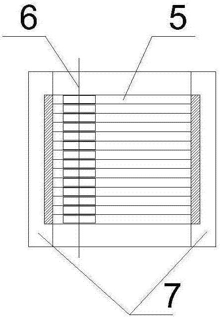
[0023] Such as figure 1 As shown, a rapid magnetic separation sewage treatment system includes a magnetic coagulation reaction device 1, a dosing device 2, a plate type magnetic separation device 3, a two-stage magnetic separation device 8 and sludge treatment equipment 9, and a magnetic coagulation reaction device 1 A dosing device 2 is provided above, and the magnetic coagulation reaction device 1 is used to form flocs from the pollutants in the sewage with magnetic powder as the core. The sewage outlet of the magnetic coagulation reaction device 1 and the sewage inlet of the plate type magnetic separation device 3 4 connected, the plate type magnetic separation device 3 includes a magnetic separation pool, a magnetic plate group 5, a slag scraper 6 and a mud collection bucket 7, the sewage inlet 4 of the plate type magnetic separation device 3 is located at the bottom of the magnetic separation pool, and the magnetic The plate group 5 is composed of several parallel magneti...


PUM


Abstract

The invention discloses a rapid magnetic separation sewage treatment system which comprises a magnetic coagulation reaction device, a dosing device, a plate-type magnetic separation device, a two-stage magnetic separation device and sludge treatment equipment, wherein the dosing device is arranged above the magnetic coagulation reaction device; the magnetic coagulation reaction device is used for enabling pollutants in sewage to form flocculates by taking magnetic powder as a core; a sewage outlet of the magnetic coagulation reaction device is connected with a sewage inlet of the plate-type magnetic separation device; the plate-type magnetic separation device comprises a magnetic separation pool, a magnetic plate group, a slag scraper and a sludge hopper; a sewage inlet of the plate-type magnetic separation device is formed in the bottom of the magnetic separation pool; the magnetic plate group is composed of a plurality of magnetic plates parallel to one another; the sludge hopper is arranged at the rear end of the magnetic plate group and connected with the two-stage magnetic separation device; and a sludge outlet of the two-stage magnetic separation device is connected with the sludge treatment equipment. According to the rapid magnetic separation sewage treatment system disclosed by the invention, the problems such as high moisture content, high sludge quantity and low magnetic recovery efficiency in the traditional sludge filtration by adopting a sedimentation basin are solved.

Description

technical field [0001] The invention relates to the technical field of magnetic separation of sewage, in particular to a rapid magnetic separation sewage treatment system. Background technique [0002] With the development of my country's economy and the accelerated pace of industrialization, my country's industrialization has brought a lot of environmental pollution, especially the pollution of water resources. Originally, my country's water resources were not rich, and a large amount of pollution caused water shortages in some areas of our country, and the conservation of polluted water resources became an imminent problem. [0003] Existing sewage treatment adopts the method of chemical reaction, but this method takes too long, the effect is too poor, and the occupied area is large, so it cannot really realize rapid sewage treatment. [0004] Patent application number: 201010251476.4 discloses a new type of magnetic separation sewage treatment device, including a tank, t...

Claims


Application Information

Patent Timeline
Patent Type & Authority Applications(China)
IPC IPC(8): C02F1/48C02F9/12C02F11/12
CPCC02F1/488C02F1/28C02F1/52C02F1/66C02F9/00C02F11/12C02F2001/007C02F2301/08
Inventor 李朝均
Owner 绵阳西真科技有限公司
Learn More