Municipal sludge drying device

A technology for drying and sludge treatment, which is applied in the fields of dewatering/drying/concentrating sludge treatment, separation of dispersed particles, chemical instruments and methods, etc. It can solve the problems of inconvenient sludge treatment, uncomfortable handling personnel, time-consuming and labor-intensive problems, etc.

Inactive Publication Date: 2017-12-15
魏亦南
View PDF4 Cites 10 Cited by
  • Summary
  • Abstract
  • Description
  • Claims
  • Application Information

AI Technical Summary

Problems solved by technology

[0005] In order to overcome the shortcomings of manual processing of sludge, which is time-consuming and labor-intensive, a large amount of sludge is inconvenient for people to handle, and the gas generated during the processing is likely to make the processing personnel feel uncomfortable, the technical problem to be solved by the present invention is to provide a It is a municipal sludge drying treatment device that saves time and labor, can make the sludge agglomerate, and is convenient for people to process. During the process, the gas that appears can be filtered and discharged, and it is not easy to make the processing personnel feel uncomfortable.

Method used


Image

  • Municipal sludge drying device
  • Municipal sludge drying device
  • Municipal sludge drying device

Examples


Embodiment 1

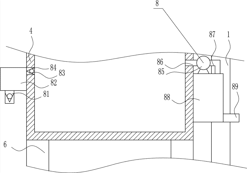
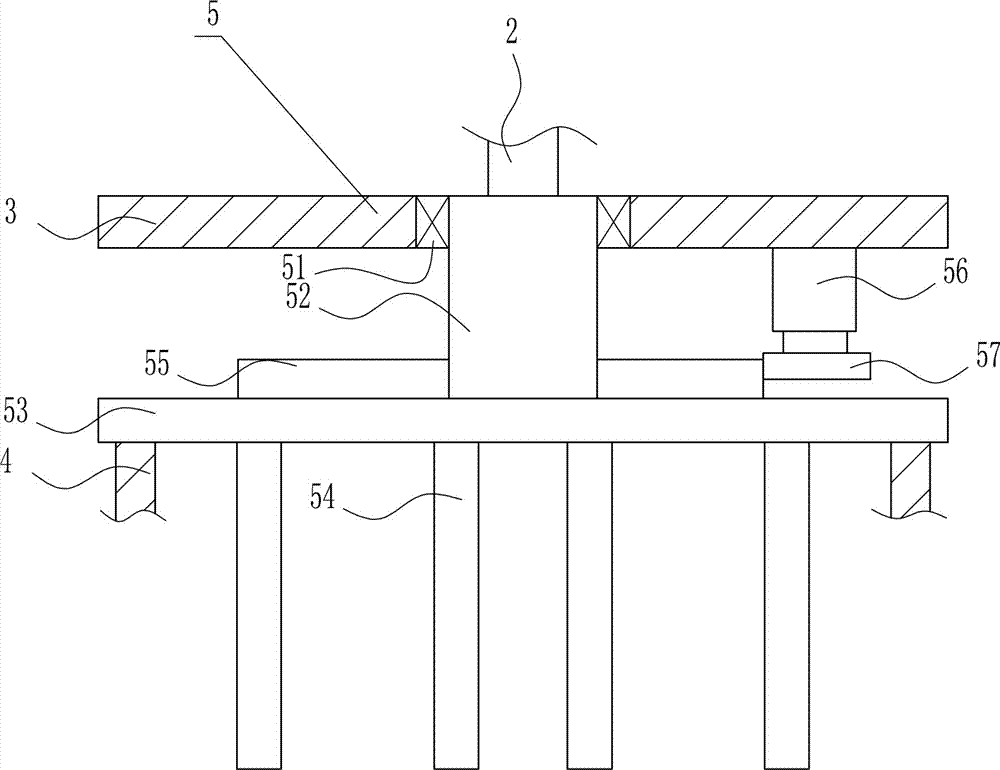
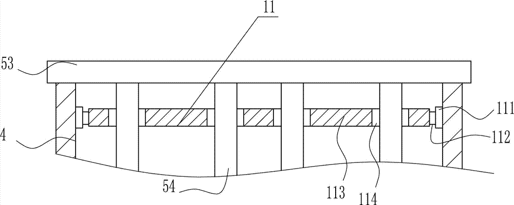
[0039] A municipal sludge drying treatment device, such as Figure 1-9 As shown, it includes an n-shaped frame 1, a cylinder 2, a horizontal plate 3, a circular frame 4, a stirring device 5, a leg 6 and a placing device 7. The inner bottom of the n-shaped frame 1 is symmetrically installed on the left and right sides. 6. A placement device 7 is provided between the inner sides of the left and right legs 6 and a circular frame 4 is installed between the top ends of the left and right legs 6. The circular frame 4 is located directly above the placement device 7, in the n-type frame 1. A cylinder 2 is installed in the middle of the top, and the cylinder 2 is arranged vertically. A horizontal plate 3 is installed on the telescopic rod of the cylinder 2, and a stirring device 5 is arranged in the middle of the bottom of the horizontal plate 3. The stirring component of the stirring device 5 is located in the circular frame 4.

Embodiment 2

[0041] A municipal sludge drying treatment device, such as Figure 1-9 As shown, it includes an n-shaped frame 1, a cylinder 2, a horizontal plate 3, a circular frame 4, a stirring device 5, a leg 6 and a placing device 7, and the inner bottom of the n-shaped frame 1 is symmetrically installed with legs on the left and right sides 6. A placement device 7 is provided between the inner sides of the left and right legs 6 and a circular frame 4 is installed between the top ends of the left and right legs 6. The circular frame 4 is located directly above the placement device 7, in the n-type frame 1. A cylinder 2 is installed in the middle of the top, and the cylinder 2 is arranged vertically. A horizontal plate 3 is installed on the telescopic rod of the cylinder 2, and a stirring device 5 is arranged in the middle of the bottom of the horizontal plate 3. The stirring component of the stirring device 5 is located in the circular frame 4.

[0042] The stirring device 5 includes a firs...

Embodiment 3

[0044] A municipal sludge drying treatment device, such as Figure 1-9 As shown, it includes an n-shaped frame 1, a cylinder 2, a horizontal plate 3, a circular frame 4, a stirring device 5, a leg 6 and a placing device 7. The inner bottom of the n-shaped frame 1 is symmetrically installed on the left and right sides. 6. A placement device 7 is provided between the inner sides of the left and right legs 6 and a circular frame 4 is installed between the top ends of the left and right legs 6. The circular frame 4 is located directly above the placement device 7, in the n-type frame 1. A cylinder 2 is installed in the middle of the top, and the cylinder 2 is arranged vertically. A horizontal plate 3 is installed on the telescopic rod of the cylinder 2, and a stirring device 5 is arranged in the middle of the bottom of the horizontal plate 3. The stirring component of the stirring device 5 is located in the circular frame 4.

[0045] The stirring device 5 includes a first bearing sea...


PUM


Abstract

The invention relates to a treating device and especially relates to a municipal sludge drying device. The technical problem to be solved by the invention is to provide the municipal sludge drying device which is time-saving and labor-saving, is capable of caking sludge for bringing convenience in treatment to people, is capable of filtering and then exhausting the gas generated in the treatment process and is difficult to cause the treatment person feel uncomfortable. In order to solve the technical problem, the municipal sludge drying device provided by the invention comprises an n-shaped frame, wherein supporting legs are symmetrically arranged on left and right sides of the bottom in the n-shaped frame; a placement device is arranged between the inner side walls of the supporting legs on left and right sides; a circular frame is arranged between the top ends of the supporting legs on left and right sides; and the circular frame is located right above the placement device. According to the invention, a filtering device is arranged for filtering and then exhausting the gas generated in the sludge treatment process, an airing device is capable of promoting the coal flaming and the sludge heating effect is better.

Description

Technical field [0001] The invention relates to a treatment device, in particular to a municipal sludge drying treatment device. Background technique [0002] Municipal administration refers to the various administrative tasks of the city. Also refers to market trade affairs; city management work. Including industry and commerce, transportation, public security, culture and education, environment, health, infrastructure, etc. [0003] In municipal engineering, a large amount of silt will appear, and the sludge needs to be treated without affecting the surrounding environment. When the sludge is processed manually, it is time-consuming and laborious, and the large amount of sludge is inconvenient for people to process. The gas generated in the process is easy to cause The handler is uncomfortable. Therefore, it is urgent to develop a time-saving and labor-saving method that can make the sludge agglomerate, which is convenient for people to process, and the gas that appears during ...

Claims


Application Information

Patent Timeline
Patent Type & Authority Applications(China)
IPC IPC(8): C02F11/12B01D46/00
Inventor 沈灿甘世昌房成洁雷铭
Owner 魏亦南
Why Eureka
Try Eureka