Bending-shearing separation control type fabricated metal damper
A metal damper, separate control technology, applied in building types, protective buildings/shelters, building components, etc., can solve the problem of low-cycle fatigue performance of dampers, out-of-plane buckling of energy-consuming panels, and large cumulative plastic deformation. and other problems, to achieve the effect of flexible design, reduced repair cost, and stable mechanical properties
- Summary
- Abstract
- Description
- Claims
- Application Information
AI Technical Summary
Problems solved by technology
Method used
Image
Examples
Embodiment 1
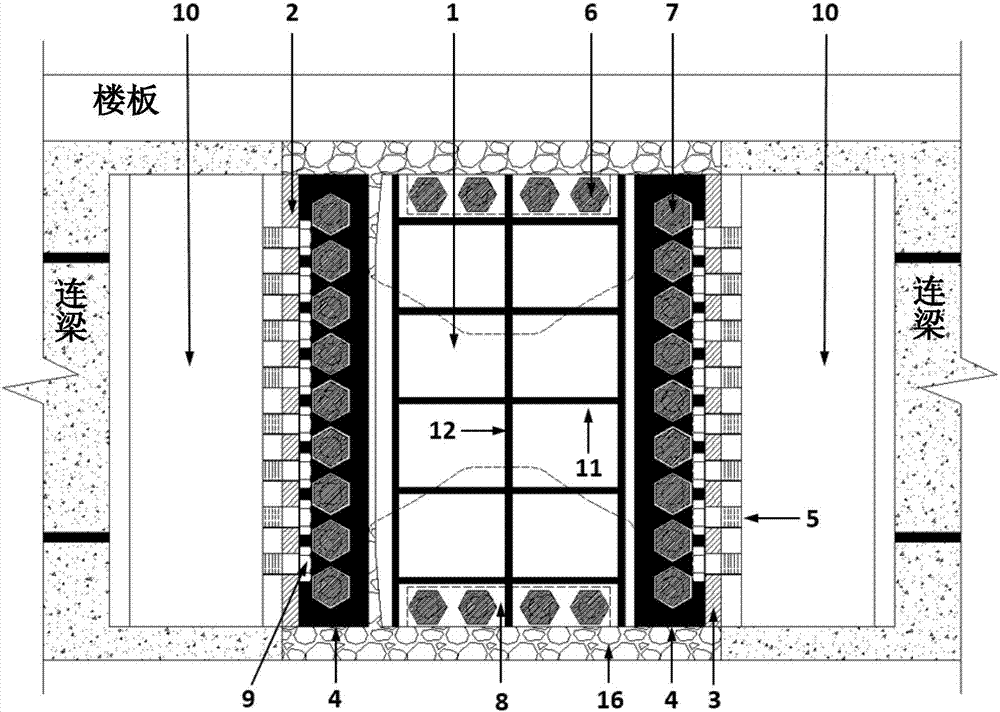
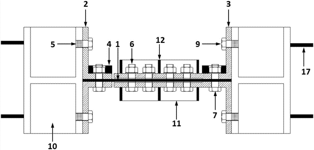
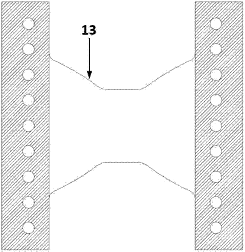
[0031] figure 1 It is a schematic diagram of the structure of this embodiment. This embodiment is composed of metal energy dissipating sheet 1, L-shaped connection support 2, integrated anti-buckling connection dual-function support 3, replaceable nut fastening plate 4, threaded hole 5, pre-compression fastening bolt 6, friction Type high-strength connecting bolt 7, backing plate 8, pressure-bearing bolt 9, connecting embedded parts 10, horizontal stiffening rib 11, longitudinal stiffening rib 12, bending-shear separation control type assembled metal damper line type 13, smooth thickness weakening Section 14, small slope edge 15, flexible filling material 16, embedded anchor steel bar 17. When assembling, the metal energy dissipating sheet 1, the backing plate 8, and the integrated anti-buckling connection dual-function support 3 are positioned and assembled according to the position of the bolt hole, and fixed by the pre-compressed fastening bolt 6. Connect the two ends of th...
Embodiment 2
[0040] Picture 9 It is a sectional view of the structure of this embodiment. Two metal energy dissipating pieces 1 are connected in parallel, the anti-buckling partition 18 and the partition 19 separate the two metal energy dissipation pieces 1, and the anti-buckling partition 18 and the integrated anti-buckling connection dual-function support 3 A backing plate 8 is provided at the pressing and fastening bolt 6 so that each energy dissipation piece does not affect each other when the damper works. The rest of the structure is the same as the first embodiment.
[0041] Picture 10 It is a schematic diagram of the anti-buckling partition 18 of this embodiment. Corresponding bolt holes are opened, and the two L-shaped connecting supports 2 are connected by friction-type high-strength connecting bolts 7, and the contact surface with the energy dissipating section of the metal energy dissipating sheet 1 has a thickness The weakened smooth section 14 prevents friction between it and ...
Embodiment 3
[0044] Picture 12 It is a schematic diagram of the structure of this embodiment. The damper is placed between the layers of the frame structure, and the displacement between the layers during the earthquake is used to drive the damper to work and dissipate energy. The upper end of the damper is connected with the upper frame beam, the lower end is connected with the concrete connecting buttress, and the concrete connecting buttress has Sufficient bearing capacity and initial stiffness to avoid exiting work before the damper yields. The dampers can be placed in parallel on the connecting buttresses. The other structure is the same as the first embodiment.
PUM
 Abstract
Description
Claims
Application Information
 - R&D
- Intellectual Property
- Life Sciences
- Materials
- Tech Scout
- Unparalleled Data Quality
- Higher Quality Content
- 60% Fewer Hallucinations
Browse by: Latest US Patents, China's latest patents, Technical Efficacy Thesaurus, Application Domain, Technology Topic, Popular Technical Reports.
© 2025 PatSnap. All rights reserved.Legal|Privacy policy|Modern Slavery Act Transparency Statement|Sitemap|About US| Contact US: help@patsnap.com


