Retention pin having foot for holding spring in disc brake pack reaction plate during assembly and for operating stator disc

A technology of reaction plate and holding pin, which is applied in the direction of brakes, brake components, hydraulic brakes, etc., and can solve the problems of stator disc wear and spring falling off, etc.

Active Publication Date: 2017-12-15
DEERE & CO
View PDF16 Cites 1 Cited by
  • Summary
  • Abstract
  • Description
  • Claims
  • Application Information

AI Technical Summary

Problems solved by technology

One current design of such an assembly, disclosed in U.S. Patent No. 8,500,591, issued August 6, 2013, has the disadvantage that the springs cause wear to the engaged stator disks and that th

Method used


Image

  • Retention pin having foot for holding spring in disc brake pack reaction plate during assembly and for operating stator disc
  • Retention pin having foot for holding spring in disc brake pack reaction plate during assembly and for operating stator disc
  • Retention pin having foot for holding spring in disc brake pack reaction plate during assembly and for operating stator disc

Examples


Embodiment Construction

[0015] can be obtained by referring to the attached Figure 1 to Figure 5 To appreciate at least one example implementation of the disclosed subject matter.

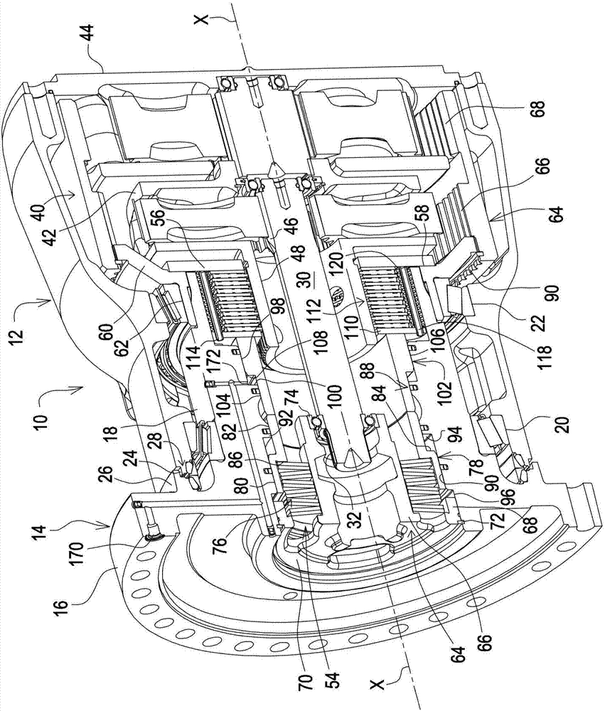
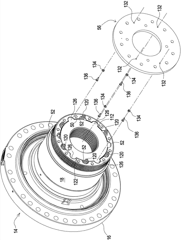
[0016] now refer to figure 1 , shows a final drive 10 comprising a bell hub 12 and a spindle 14 comprising an annular mounting flange 16 comprising a plurality of mounting holes and Connected to and project radially from the inner end of a generally cylindrical section 18 of a spindle extending axially within the smaller end of the bell-shaped hub 12 . The spindle 14 is adapted to be mounted to a vehicle chassis (not shown) by inserting fasteners through mounting holes in the flange 16 .

[0017] The hub 12 is supported for rotation about the cylindrical section 18 of the mandrel by an axially inner tapered roller bearing 20 and an axially outer tapered roller bearing 22, respectively, wherein the inner end of the hub 12 is located radially outward of the inner roller bearing 20 and is supported by the shaft. An inwar...


PUM


Abstract

The invention relates to a retention pin having a foot for holding a spring in a disc brake pack reaction plate during assembly and for operating a stator disc. A friction drive arrangement includes a plurality of interleaved rotor and stator discs. An end stator disc is adjacent a reaction plate containing a plurality of cylindrical, stepped bores defining spring receptacles opening toward the end stator disc and pin guide holes opening in an opposite direction. Each receptacle contains a coil compression spring located between a bottom of the receptacle and a spring retention pin having a first end section reciprocably received in the guide hole and having a second end section defined by a large diameter foot located between an end of the spring and the end stator disc, with the foot being configured for directly engaging the end stator disc. A tool is used to retract the pins and associated springs into the associated receptacles so as to retain the springs during assembly. Excess retraction of the pins is prevented for preventing over-compression of the springs.

Description

technical field [0001] The present application generally contemplates disc clutches or brakes. Background technique [0002] Friction drive devices sometimes include helical compression springs mounted in cylindrical spring housings provided in the reaction plate of the device and having ends that bear directly against the stator discs of a disc clutch or brake. One current design of such an assembly, disclosed in U.S. Patent No. 8,500,591, issued August 6, 2013, has the disadvantage that the springs cause wear to the engaged stator disks and that the springs tend to dislodge from the springs of the reaction plates during assembly. Falling off in the receiver (currently use grease or petroleum jelly to keep the spring in the receiver). [0003] What is needed, therefore, is a disc clutch or brake assembly of the type described that does not suffer from the disadvantages noted above. Contents of the invention [0004] According to a first aspect there is provided a brake ...

Claims


Application Information

Patent Timeline
IPC IPC(8): F16D55/36F16D65/14
CPCF16D55/36F16D65/14B60T1/062F16D55/40F16D2250/0084F16D65/005F16D2055/007
Inventor A·B·斯蒂芬斯J·S·特纳
Owner DEERE & CO
Why Eureka
Try Eureka