Washing device of fan coil

A technology of fan coil unit and cleaning device, which is applied in the direction of cleaning heat transfer device, noise suppression, space heating and ventilation, etc. It can solve the problems of high operation requirements and difficult operation, so as to improve heat exchange efficiency and eliminate noise Effect, dust removal and sterilization thorough effect

Inactive Publication Date: 2017-12-15
QINGDAO UNIV
View PDF2 Cites 10 Cited by
  • Summary
  • Abstract
  • Description
  • Claims
  • Application Information

AI Technical Summary

Problems solved by technology

[0005] The patent number is "CN 205784837U", and the name is "A Fan Coil Cleaning Device". The cleaning method still requires manual operation, and it is nece

Method used


Image

  • Washing device of fan coil
  • Washing device of fan coil
  • Washing device of fan coil

Examples


specific Embodiment approach 1

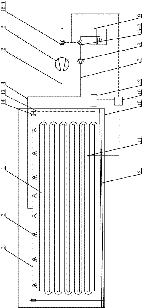
[0030] Specific implementation mode one, such as Figure 1~5 As shown, a cleaning device for a fan coil unit of the present embodiment is composed of a coil tube 1, a nozzle array tube 2, a nozzle 3, a delivery pipeline 4, a compressor 5, an air suction pipeline 6, a water suction pipeline 7, a water pump 8, Detergent storage box 9, controller 10, dirt detection device 11, motor 12, transmission mechanism 13, slider 14, guide rod 15, valve one 16-1, valve two 16-2, brush rod 17, worm Shell one 18-1, volute two 18-2, air outlet blade 19, air outlet blade adjustment device 20, groove 21, brush 22, rotating shaft 23 and air source 24, the compressor 5 is arranged on the suction On the gas pipeline 6; the valve one 16-1 is arranged on the suction pipeline 6, and is located between the compressor 5 and the air source 24; the delivery pipeline 4 communicates with the suction pipeline 6; the described The conveying pipeline 4 communicates with the nozzle array pipe 2; the uniform ar...

specific Embodiment approach 2

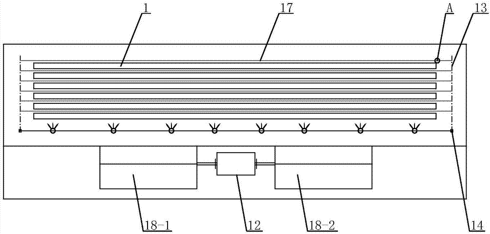
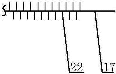
[0031] Specific implementation mode two, such as Figure 2~3 As shown, a cleaning device for a fan coil unit according to this embodiment also includes a brush rod 17 and a brush 22, and the brush rod 17 communicates with the transmission mechanism 13; the brush rod The rods 17 are arranged between the tube disks 1; the transmission mechanism 13 is connected with the motor 12; the brush rod 17 is provided with a soft brush 22.

specific Embodiment approach 3

[0032] Specific implementation mode three, such as Figure 5 As shown, a cleaning device for a fan coil unit in this embodiment also includes an air outlet blade 19 and an air outlet blade adjustment device 20. The air outlet blade adjustment device 20 can adjust the inclination angle of the air outlet blade 19 Realize the fully enclosed effect of the fan coil unit.


PUM


Abstract

A cleaning device for a fan coil unit. The invention belongs to the field of fan coil cleaning. The purpose of the present invention is to provide a cleaning device for fan coils, which can automatically clean the fan coils and ensure the cleanliness of the air from the fan coils. The device of the present invention is composed of coil pipe, nozzle array pipe, nozzle, conveying pipeline, compressor, suction pipeline, water suction pipeline, water pump, detergent storage tank, controller, dirt detection device, motor, transmission mechanism, slider, guide Rod, valve one, valve two, brush rod, volute one, volute two, air outlet blade, air outlet blade adjustment device, groove and hair brush. The invention utilizes high-pressure air flow washing, brush contact wiping and cleaning, and detergent atomization and spraying technologies, and uses the electric signal loop of the controller to control and adjust the equipment, thereby realizing automatic cleaning of the fan coil unit and ensuring efficient dust removal and cleaning. Sterilize. The invention is suitable for the heating and cooling system of the terminal wind disk.

Description

technical field [0001] This patent relates to a cleaning device for fan coil units, belonging to the field of fan coil unit cleaning. Background technique [0002] As the terminal device of the air conditioning system, the fan coil unit is widely used in the heating and cooling system of the building. The fan coil unit is installed indoors, and generally when the fan coil unit is turned on, the doors and windows in the room are closed, so the wind blown by the fan has a major and direct impact on the cleanliness of the room. The wind disk that has not been cleaned for a long time not only accumulates dust but also a lot of bacteria and molds, etc., which are carried into the room by the wind of the fan, and pose a huge threat to physical and mental health after being breathed into the body. In addition, the attachment of a large amount of dust and bacteria will greatly reduce the heat exchange efficiency, waste energy and shorten the life of the equipment. In order to prev...

Claims


Application Information

Patent Timeline
IPC IPC(8): F24F1/00F24F11/00F24F13/24F28G13/00F28G15/00
CPCF24F1/0007F24F13/24F24F2013/247F24F2221/22F24F2221/225F28G13/00F28G15/003
Inventor 武潇鞠继升吴荣华
Owner QINGDAO UNIV
Why Eureka
Try Eureka