
Pressure relief protection system for CEMS (continuous emission monitoring system) back blowing unit

A protection system and pressure relief technology, applied in the field of CEMS systems, can solve problems such as pressure relief, damage to sampling and analysis unit equipment, etc., and achieve the effect of avoiding damage

Pending Publication Date: 2017-12-15
ANHUI BISHUI ELECTRONICS TECH
View PDF7 Cites 1 Cited by
  • Summary
  • Abstract
  • Description
  • Claims
  • Application Information

AI Technical Summary

Problems solved by technology

[0003] The conventional CEMS system will automatically switch to the sampling state after the backflushing is completed. When the sampling gas path is normal, the backflushing gas will not affect the sampling pipeline. When blowing fails to clear the blockage, the high-pressure backflush gas will stay in the sampling pipeline to form a pressure. When the system switches to the sampling state, the gas pressure will release to the pipeline of the sampling and analysis unit, which will affect the sampling and analysis. Damage to some equipment of the unit

Method used


Image

  • Pressure relief protection system for CEMS (continuous emission monitoring system) back blowing unit

Examples


Embodiment Construction

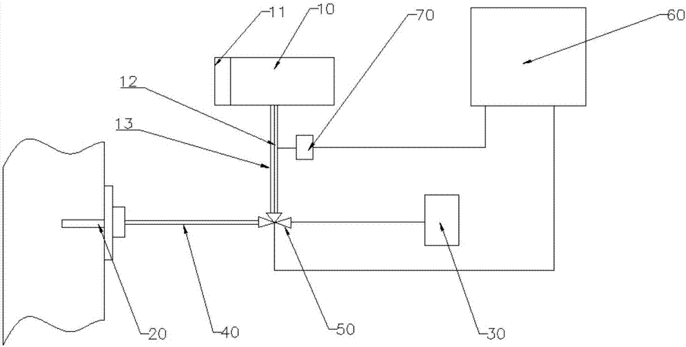
[0017] Such as figure 1 As shown, a structural schematic diagram of a CEMS blowback unit pressure relief protection system, in this embodiment, includes a blowback gas source 10, a sampling probe 20, a sampling analysis unit 30, and a heat tracing pipe 40, and also includes a two-position three-way electromagnetic The valve 50 and the controller 60, the ports of the two-position three-way solenoid valve 50 are respectively connected to the heat tracing pipe 40, the backflush gas source 10 and the sampling and analysis unit 30, and the sampling probe 20 is connected to the two-position three-way solenoid valve 50 through the heat tracing pipe 40 , and a pressure relief device 70 is provided between the blowback gas source 10 and the two-position three-way solenoid valve 50, the two-position three-way solenoid valve 50 and the pressure relief device 70 are both electrically connected to the controller 60, and the pressure relief device 70 includes The pressure relief valve, the ...


PUM


Abstract

The invention provides a pressure relief protection system for a CEMS (continuous emission monitoring system) back blowing unit, and belongs to the technical field of CEMS systems. The pressure relief protection system comprises a back blowing gas source, a sampling probe, a sampling and analyzing unit and a heat tracing pipe, and further comprises a two-position three-way electromagnetic valve and a controller, wherein the ports of the two-position three-way electromagnetic valve are connected with the heat tracing pipe, the back blowing gas source and the sampling and analyzing unit respectively; the sampling probe is connected with the two-position three-way electromagnetic valve through the heat tracing pipe; a pressure relief device is arranged between the back blowing gas source and the two-position three-way electromagnetic valve; and the two-position three-way electromagnetic valve and the pressure relief device are electrically connected with the controller. The pressure relief protection system is used for reducing damage of back blowing gas to sampling and analyzing unit equipment in the case of gas channel blockage.

Description

technical field [0001] The invention belongs to the technical field of CEMS systems, and in particular relates to a CEMS blowback unit pressure relief protection system. Background technique [0002] At present, with the continuous improvement of environmental protection requirements, in order to ensure that my country's key pollution source flue gas emission industries are developing in a green and pollution-free direction, the industrial factories involved in flue gas emissions have installed flue gas online monitoring systems (CEMS, Continuous Emission Monitoring System), and use the CEMS to sample and detect the smoke that needs to be discharged into the atmosphere in real time, which can prevent toxic gases from entering the atmosphere and polluting the environment. [0003] The conventional CEMS system will automatically switch to the sampling state after the backflushing is completed. When the sampling gas path is normal, the backflushing gas will not affect the sampli...

Claims


Application Information

Patent Timeline
Patent Type & Authority Applications(China)
IPC IPC(8): G01N33/00B08B9/032
CPCG01N33/0029B08B9/0321
Inventor 秦汉林翟湘毅吴为江徐猛
Owner ANHUI BISHUI ELECTRONICS TECH
Learn More