
A Voltage Equalizing Circuit for DC Capacitor Bank of Multilevel Converter

A DC capacitor and voltage equalizing circuit technology, applied in the direction of converting AC power input to DC power output, electrical components, output power conversion devices, etc., can solve the problems of increasing volume and weight, and achieve the purpose of retaining degrees of freedom and improving power density , The effect of reducing power loss

Active Publication Date: 2019-07-30
INST OF ELECTRICAL ENG CHINESE ACAD OF SCI +1
View PDF8 Cites 0 Cited by
  • Summary
  • Abstract
  • Description
  • Claims
  • Application Information

AI Technical Summary

Problems solved by technology

However, similar to the circuit described in literature [1], this circuit still realizes energy transfer between DC capacitors through energy storage inductors, and its disadvantages are: (1) The introduction of floating capacitors is mainly used to balance the voltage stress of power switching devices; (2) The voltage balance of the DC capacitor is still realized by transferring energy through the energy storage inductance in the equalizing circuit unit. The introduction of the floating capacitor increases the volume and weight of the system; (3) After the introduction of the floating capacitor, the equalizing circuit unit The voltage stress of the inductance element is still a quarter of the DC bus voltage, so it is still necessary to set a larger energy storage inductor to limit the rate of change of the energy storage inductor current

Method used


Image

  • A Voltage Equalizing Circuit for DC Capacitor Bank of Multilevel Converter
  • A Voltage Equalizing Circuit for DC Capacitor Bank of Multilevel Converter
  • A Voltage Equalizing Circuit for DC Capacitor Bank of Multilevel Converter

Examples


Embodiment Construction

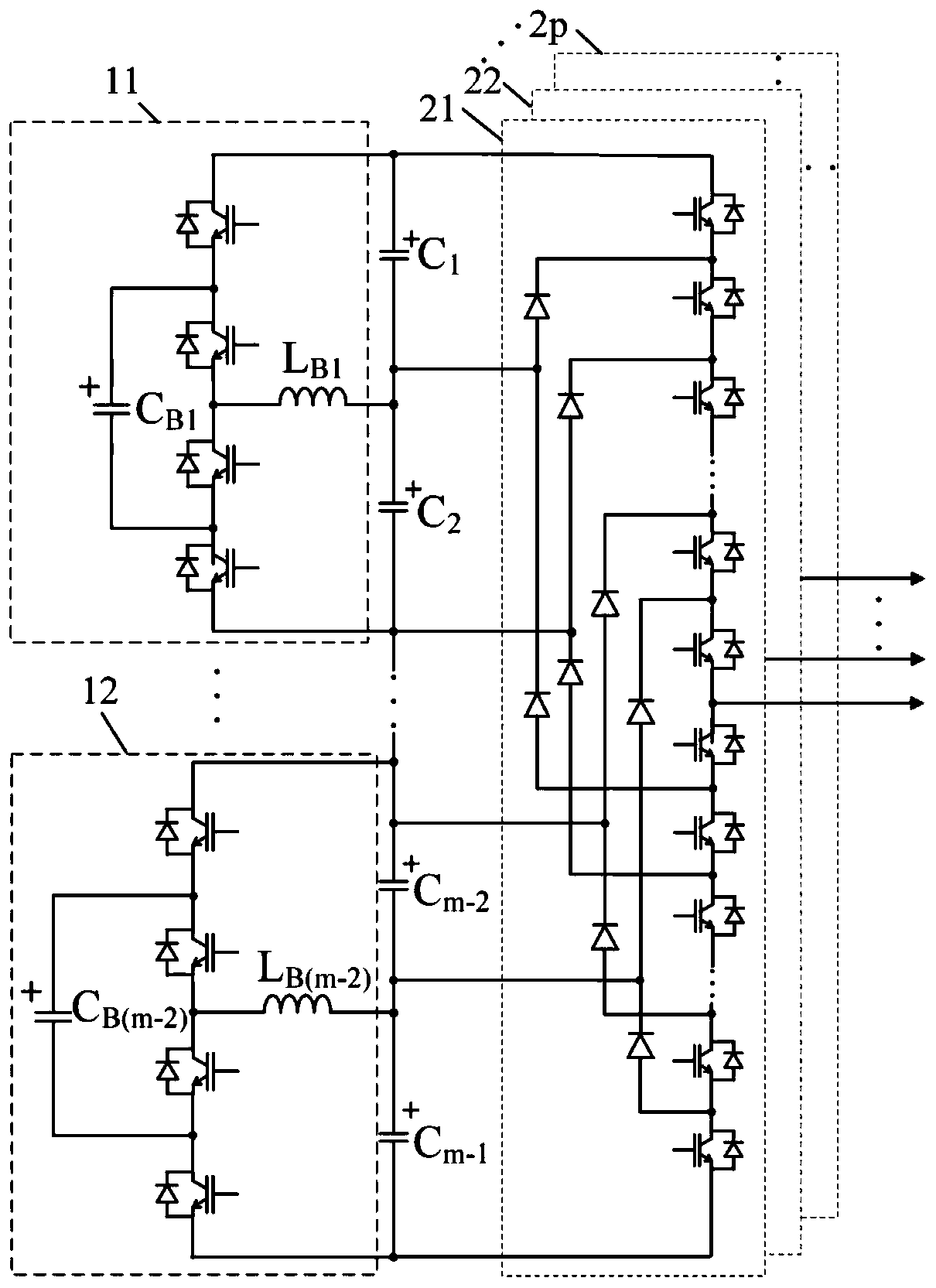
[0031] The voltage equalizing circuit of the DC capacitor bank of the multilevel converter proposed by the present invention is used in the circuit schematic diagram of the p-phase m-level diode-clamped multilevel converter. figure 1shown. The DC capacitor bank of p-phase m-level diode-clamped multilevel converter consists of m-1 DC capacitors C i Composed in series, i=1, 2,..., m-1, and m-2 groups of voltage equalizing circuit units are configured to realize the voltage balance of multiple DC capacitors of the multi-level converter. Any two adjacent DC capacitors of the DC capacitor bank are connected to a voltage equalizing circuit unit. The control terminal of each power switching device of the m-2 voltage equalizing circuit units is connected to the control device of the multilevel converter.

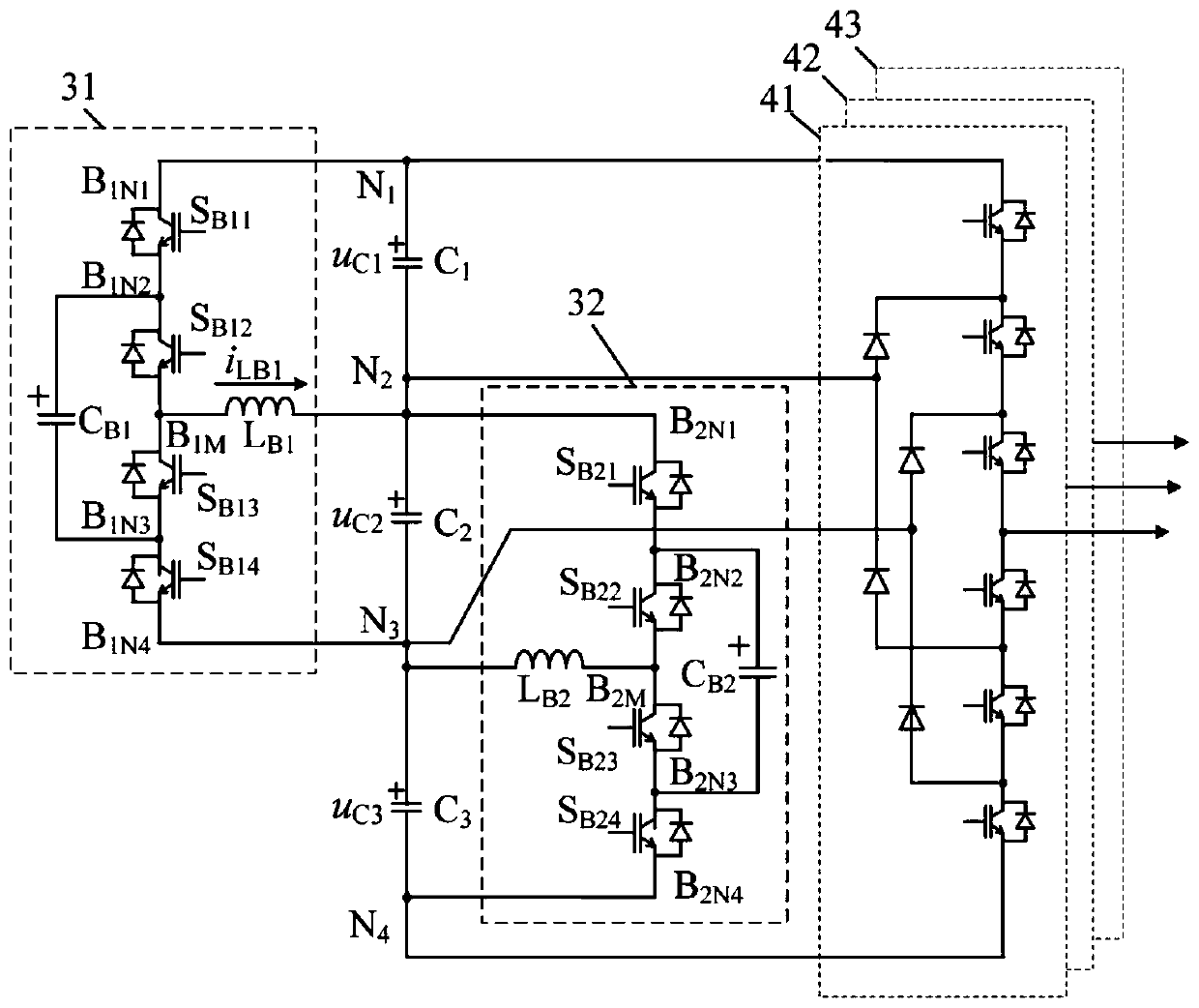
[0032] Such as figure 2 As shown, a specific embodiment of the present invention is: a voltage equalizing circuit of a 4-level converter DC capacitor bank, which is used for bal...


PUM


Abstract

A multi-level converter DC capacitor bank voltage sharing circuit outputs m levels, wherein m>=3; the DC capacitor bank is formed by connecting m-1 DC capacitors Ci in series, wherein i=1, 2.., m-1; m-2 voltage-sharing circuits are configured, thus realizing voltage balance of the multi-level converter DC capacitors; two random adjacent capacitors of the DC capacitor bank are respectively connected with one voltage-sharing circuit unit; according to a current limiting inductance current direction, when an auxiliary voltage sharing capacitor voltage is bigger than a reference voltage, the auxiliary voltage sharing capacitor discharges power to the DC capacitor bank through the current limiting inductance; when the auxiliary voltage sharing capacitor voltage is smaller than the reference voltage, the DC capacitor bank charges the auxiliary voltage sharing capacitor through the current limiting inductance, thus controlling voltage balance of the DC capacitor bank. A control algorithm with the overcurrent restriction capability is employed, so the voltage sharing circuit can ensure the multi-level converter DC capacitor bank voltage balance under a random modulation ratio and power factors.

Description

technical field [0001] The invention relates to a voltage balancing device of a DC capacitor bank of a multilevel converter, in particular to a voltage balancing device of a DC capacitor bank of a diode-clamped multilevel converter. Background technique [0002] The DC capacitor bank of the diode-clamped multilevel converter is composed of multiple DC capacitors connected in series. Both ends of the DC capacitor bank are connected to the DC power supply. connected to the clamping diode network of the leveling converter. The bridge arm of the multilevel converter is composed of a plurality of power switching devices connected in series and corresponding clamping diode networks, and the control terminals of the power switching devices are connected with the control device of the multilevel converter. By changing the switching state of the power switching device of the bridge arm through the control device, multiple level values ​​generated by the voltage of the DC capacitor g...

Claims


Application Information

Patent Timeline
Patent Type & Authority Patents(China)
IPC IPC(8): H02M7/487H02M1/32
CPCH02M1/32H02M7/487
Inventor 葛琼璇崔冬冬
Owner INST OF ELECTRICAL ENG CHINESE ACAD OF SCI
Learn More