
Short-edge cutting broaching finishing broach and short-edge cutting combined broaching finishing broach

A technology of fine broaching and cutting edge, applied in the field of short-edge cutting broaching fine broaching and short-edge cutting combined broaching fine broaching, can solve the problems of cylinder slide groove parallelism and poor surface roughness, etc. The effect of increased tool life, comprehensive cost-effectiveness, and improved use effect

Active Publication Date: 2017-12-19
CHENGDU GERUN HI TECH MATERIALS
View PDF5 Cites 1 Cited by
  • Summary
  • Abstract
  • Description
  • Claims
  • Application Information

AI Technical Summary

Problems solved by technology

[0004] The purpose of the present invention is to provide a short-edge cutting broaching broaching tool and a short-edge cutting combined broaching finishing broach to solve the problem of out-of-tolerance parallelism and surface roughness of the cylinder slide groove when using traditional cutting tools

Method used


Image

  • Short-edge cutting broaching finishing broach and short-edge cutting combined broaching finishing broach
  • Short-edge cutting broaching finishing broach and short-edge cutting combined broaching finishing broach
  • Short-edge cutting broaching finishing broach and short-edge cutting combined broaching finishing broach

Examples


Embodiment 1

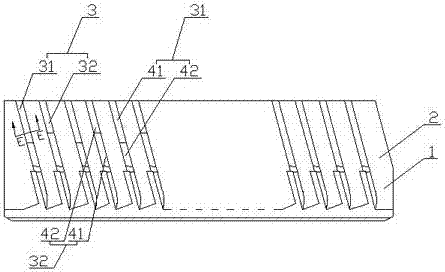
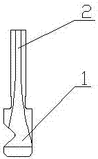
[0031] Such as figure 1 , 2 As shown in , 5, the short-edge cutting broaching finishing broach includes a support part 1, a broach part 2 is arranged on the support part 1, and a cutting tooth 3 is arranged on the broach part 2, and the cutting tooth 3 is pressed according to the workpiece to be processed. The contact sequence consists of odd-numbered cutting teeth 31 and even-numbered cutting teeth 32; wherein both odd-numbered cutting teeth 31 and even-numbered cutting teeth 32 are composed of interconnected cutting edge portions 41 and non-cutting edge portions 42, wherein the cutting edges on odd-numbered cutting teeth 31 The cutting edge portion 41 and the cutting edge portion 41 on the even-numbered cutting teeth 32 are staggered from each other.

[0032] In this embodiment, since most powder metallurgy cylinders are small in size and low in cylinder height, the traditional finishing broach is prone to the phenomenon that the parallelism is out of tolerance when machini...

Embodiment 2

[0034] Such as figure 1 , 2 , 5, compared with embodiment 1, the present embodiment optimizes the broach part 2, the broach part 2 is sheet-shaped, and the cutting teeth 3 are arranged symmetrically on both sides of the broach part 2; in the broach part On one side of 2: the non-cutting edge portion 42 on the odd-numbered cutting teeth 31 is set close to the support portion 1, and the cutting edge portion 41 on the even-numbered cutting teeth 32 is set close to the support portion 1.

Embodiment 3

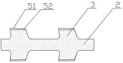
[0036] Such as image 3 As shown, compared with Embodiment 2, this embodiment optimizes the cutting edge portion 41 and the non-cutting edge portion 42, and the edge between the cutting edge 51 on the cutting edge portion 41 and the non-cutting edge 52 on the non-cutting edge portion 42. The difference in width and height is 0.02-0.05mm; in this way, the broach will not appear to let the knife and resonate in the process of broaching, and this cutting edge cutting form is conducive to chip breaking of iron chips and avoids sticking of the cutting edge. chipping phenomenon.


PUM


Abstract

The invention discloses a short-edge cutting broaching finishing broach and a short-edge cutting combined broaching finishing broach. The short-edge cutting broaching finishing broach comprises a support part, wherein a broaching part is arranged on the support part; cutting teeth are arranged on the broaching part; the cutting teeth are composed of odd number of cutting teeth and even number of cutting teeth in the sequence of contacting with a processed workpiece; the odd number of cutting teeth and the even number of cutting teeth are composed of cutting edge parts and non-cutting edge parts in mutual connection with each other; the cutting edge parts on the odd number of cutting teeth and the cutting edge parts on the even number of cutting teeth are arranged in a staggered form. The invention has the following beneficial effects: the service life of the broach of a slide sheet slot of a cylinder of a compressor of an air conditioner is prolonged in the manner of designing the tool cutting edge inclination and arranging the tool cutting edge inclinations on different cutting parts so that the phenomena of ultralow depth of parallelism and surface roughness of the slide sheet slot of the cylinder can be avoided.

Description

technical field [0001] The invention relates to the field of tool processing, in particular to a short-edge cutting broaching finish broach and a short-edge cutting combined broaching finish broach. Background technique [0002] In the air-conditioning compressor industry, most of the machining of cylinder slide grooves is done by high-speed steel broaches. However, with the implementation of the national policy of "going home appliances to the countryside" to benefit the people, the price of air conditioners has also begun to decrease. In order to save more costs, air-conditioning compressor companies began to reduce their production costs by changing the material of the cylinder and lowering the purchase price of the tool, so the powder metallurgy cylinder came into being. Compared with the traditional cast iron material, the cylinder made of this material is easy to form by die-casting, and the casting cost is lower. However, due to the performance of powder metallurg...

Claims


Application Information

Patent Timeline
Patent Type & Authority Applications(China)
IPC IPC(8): B23D43/02
CPCB23D43/02
Inventor 柳军贤
Owner CHENGDU GERUN HI TECH MATERIALS
Learn More