Headrest assembly of child car seat
A child car seat and component technology, which is applied to child seats, vehicle seats, vehicle parts, etc., can solve the problems of children's head protection and the inability to adjust the height of the headrest, so as to improve mechanical strength and wear resistance. Reasonable performance, structural design, and the effect of improving safety performance
- Summary
- Abstract
- Description
- Claims
- Application Information
AI Technical Summary
Problems solved by technology
Method used
Image

Examples
Embodiment 1
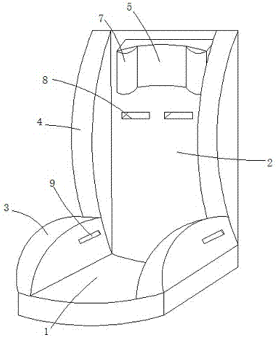
[0030] see Figure 1 to Figure 4 , the present invention provides a child car seat, comprising: a base 1, a backrest 2 connected to the base 1, two first siderests 3 respectively arranged on both sides of the base 1, and two first siderests 3 respectively arranged on the backrest 2 Two second side rests 4 on both sides, a headrest 5 arranged on the backrest 2 and capable of sliding along the backrest 2, a headrest arranged in the backrest 2 and connected to the headrest 5 Sliding device 6, flexible protective pads 7 arranged on both sides of the headrest 5;
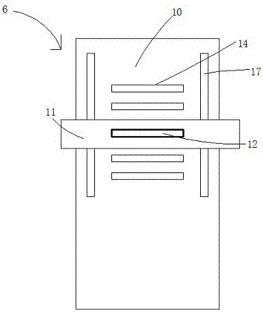
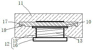
[0031] The headrest sliding device 6 includes: a sliding plate 10, a sliding sleeve 11 sleeved on the sliding plate 10, a fixing pin 12 set on the sliding sleeve 11, and a sliding sleeve sleeved on the fixing pin 12. the spring 13;
[0032] The sliding plate 10 is provided with a plurality of sockets 14 arranged in sequence along the vertical direction to cooperate with the fixed pin 12. The fixed pin 12 includes: a pin...
Embodiment 2
[0036] A manufacturing process of a headrest of a child car seat, the steps are as follows:
[0037] ①, structure and molding
[0038] The headrest assembly is placed on the backrest and can slide along the backrest. The backrest is provided with a headrest sliding device connected with the headrest; the headrest sliding device includes a sliding plate, a sliding sleeve set on the sliding plate, and a The fixed pin on the sliding sleeve and the spring sleeved on the fixed pin; the sliding plate is provided with a plurality of jacks arranged in sequence along the vertical direction to cooperate with the fixed pin; the fixed pin includes a pin rod, which is arranged on the pin rod The two flanges arranged at intervals, the fixing pin is inserted into the sliding sleeve, and the two flanges are respectively located on the inner and outer sides of the sliding sleeve, the spring is arranged between the flange on the inner side of the sliding sleeve and the sliding sleeve, and the s...
PUM
 Abstract
Description
Claims
Application Information
 - R&D
- Intellectual Property
- Life Sciences
- Materials
- Tech Scout
- Unparalleled Data Quality
- Higher Quality Content
- 60% Fewer Hallucinations
Browse by: Latest US Patents, China's latest patents, Technical Efficacy Thesaurus, Application Domain, Technology Topic, Popular Technical Reports.
© 2025 PatSnap. All rights reserved.Legal|Privacy policy|Modern Slavery Act Transparency Statement|Sitemap|About US| Contact US: help@patsnap.com