Medical catheter winding rotary table used for automatic production

A medical catheter and turntable technology, applied in the direction of conveying filamentous materials, thin material handling, transportation and packaging, etc., can solve the problems of messing up the catheter, affecting the production efficiency, affecting the operation process, etc., and achieving enhanced versatility and ingenious structure. , the effect of convenient operation

Active Publication Date: 2017-12-19
泰兴市智谷科技孵化器中心
View PDF5 Cites 8 Cited by
  • Summary
  • Abstract
  • Description
  • Claims
  • Application Information

AI Technical Summary

Problems solved by technology

[0003] Some winding carousels use the lifting of the pole to separate the coiled catheter from the pole. At this time, the catheter in a tight state will rub against the pole, making it difficult to take out the catheter or causing damage to the surface of the catheter and messing up the catheter ;
[0004] Some other winding carousels use the deflection of the pole to separate the coiled catheter from the pole, but the pole cannot be effectively fixed during the winding operation of this type of device, and the pole will deflect when the catheter is wound tightly , the coiled catheter is loose and irregular; due to its structural limitations, an additional positioning device needs to be installed to solve this problem. In addition, when the catheter is taken out after the coil is completed, it is necessary to separate the multiple poles. Only by operating can all the rods be separated from the catheter, which is not conducive to the efficiency of th

Method used


Image

  • Medical catheter winding rotary table used for automatic production
  • Medical catheter winding rotary table used for automatic production
  • Medical catheter winding rotary table used for automatic production

Examples


Embodiment Construction

[0015] The specific implementation manners of the present invention will be described in further detail below in conjunction with the accompanying drawings.

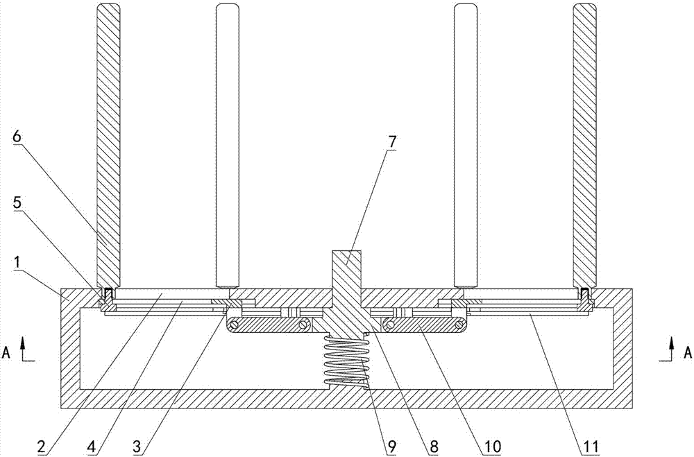
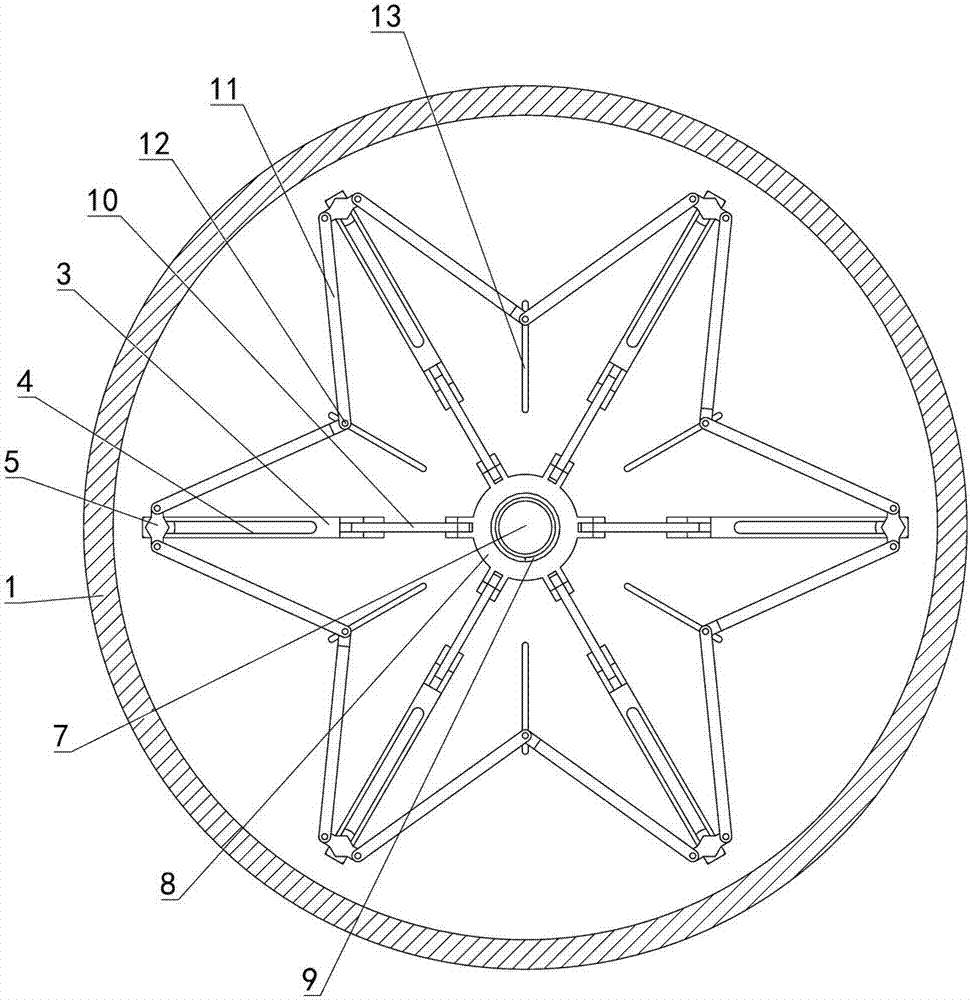
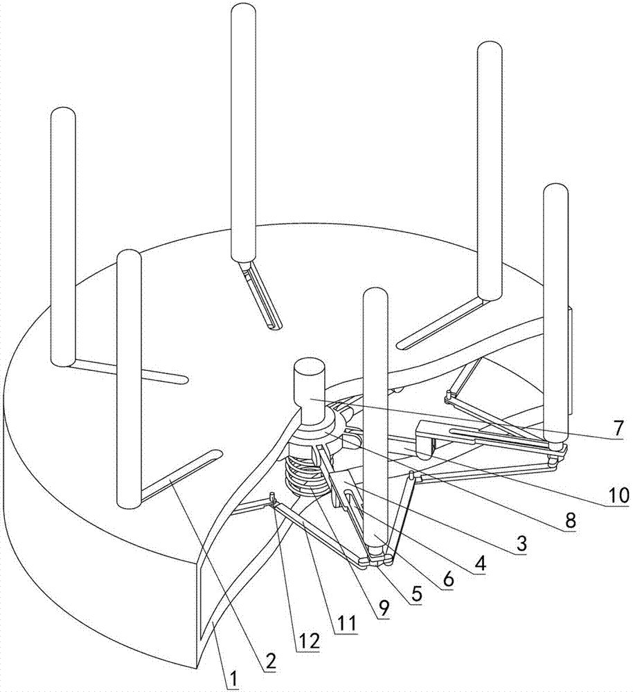
[0016] Depend on Figure 1 to Figure 4 Given, the present invention includes a turntable 1 with a cavity. The upper end surface of the turntable 1 is provided with a plurality of centripetal chutes 2 that run through the upper part of the turntable 1 and are circumferentially distributed. The centripetal chute 2 is equipped with a The slide block 3 sliding horizontally in the slot 2 is provided with a straight slot 4 vertically penetrating the slide block 3. The length direction of the straight slot 4 is consistent with the length direction of the centripetal chute 2. A vertically arranged bolt 5 sliding horizontally in the straight groove 4, a vertically arranged strut 6 is arranged above the slide block 3, and the lower end of the strut 6 is threadedly connected with the bolt 5;

[0017] Said turntable 1 has a pressin...


PUM


Abstract

The invention relates to a medical catheter winding rotary table used for automatic production. The medical catheter winding rotary table comprises a rotary table body with a cavity. Multiple centripetal slide grooves are formed in the upper end face of the rotary table body. Slide blocks capable of sliding in the centripetal slide grooves are installed in the centripetal slide grooves. Vertical through straight grooves are formed in the slide blocks. Bolts capable of sliding in the straight grooves are arranged in the straight grooves. Supporting rods vertically arranged are arranged above the slide blocks. The lower ends of the supporting rods are connected with the bolts through threads. A pressing rod vertically piercing into the cavity downwards is arranged on the rotary table body. A flange arranged in the cavity is arranged on the pressing rod. The pressing rod is sleeved with a spring. The two ends of the spring make contact with the flange and the lower end face of the cavity correspondingly. Multiple connection rods arranged in the cavity are installed on the pressing rod. Each connection rod corresponds to the corresponding centripetal slide groove in a one-to-one correspondence manner. One end of each connection rod is hinged to the pressing rod, and the other end of each connection rod is hinged to the corresponding slide block. The medical catheter winding rotary table is ingenious in structure, convenient and rapid to operate, not capable of causing the situation that it is difficult to take out catheters or surfaces of the catheters are damaged, and high in universality.

Description

technical field [0001] The invention relates to the technical field of medical device production equipment, in particular to a medical catheter winding turntable for automatic production. Background technique [0002] In the production process of medical catheters, in order to facilitate the storage, inventory and transportation of finished or semi-finished products, they usually need to be wound and packaged for the next step of the production process or out-of-warehouse operations. At present, there are many types of medical catheter winding equipment, but their core parts, namely the winding turntable, are similar. This type of winding turntable can wind the medical catheter around the support rod, and then make the wound medical catheter and the support rod The rod is separated so that the manipulator can remove the wound medical catheter for the next step; however, this type of winding carousel has the following disadvantages: [0003] Some winding carousels use the li...

Claims


Application Information

Patent Timeline
IPC IPC(8): B65H67/04B65H54/02
CPCB65H54/02B65H67/0411B65H2701/33
Inventor 张西洁
Owner 泰兴市智谷科技孵化器中心
Why Eureka
Try Eureka