
High-rise construction cantilever extending device

A cantilever device, high-rise technology, applied in the directions of construction, scaffolding accessories, housing structure support, etc., can solve the problems of unscientific structural design, small weighing range, high size requirements, and achieve novel structural design, simple and fast installation, and transmission. Stable and efficient effect

Pending Publication Date: 2017-12-19
ZHENGZHOU UNIV
View PDF11 Cites 1 Cited by
  • Summary
  • Abstract
  • Description
  • Claims
  • Application Information

AI Technical Summary

Problems solved by technology

[0002] With the development of society and the improvement of people's living standards, in order to alleviate the housing problems caused by dense population, high-rise buildings have been built. Cantilever devices are often used in the later construction of high-rise buildings. However, the cantilever devices currently used are not suitable for structural design. Science, resulting in uneven force, too large device and other problems, seriously restricting its use and development in this field
[0003] In order to solve the above problems, the present invention is proposed, which overcomes the current cantilever device. Due to the design of the diagonal stay rod, the size requirements of the diagonal stay rod are high, and the weighing range is small, resulting in long installation time during installation, commissioning and use, and the connection strength is affected. The problem of component damage caused by uneven force solves the problems of the current cantilever device, which cannot continue the construction work of the cantilever in the operating environment, and improves the current cantilever device. Since most of the cantilever devices are fixed by tools, it is difficult to use and causes problems during use. The mechanical damage and time waste caused by frequent use of tools make the present invention have the advantages of novel structural design, stable and efficient transmission, simple and fast installation, small size, high strength, and construction in the operating environment.

Method used


Image

  • High-rise construction cantilever extending device
  • High-rise construction cantilever extending device
  • High-rise construction cantilever extending device

Examples


Embodiment Construction

[0017] The following will clearly and completely describe the technical solutions in the embodiments of the present invention with reference to the accompanying drawings in the embodiments of the present invention. Obviously, the described embodiments are only some, not all, embodiments of the present invention. Based on the embodiments of the present invention, all other embodiments obtained by persons of ordinary skill in the art without making creative efforts belong to the protection scope of the present invention.

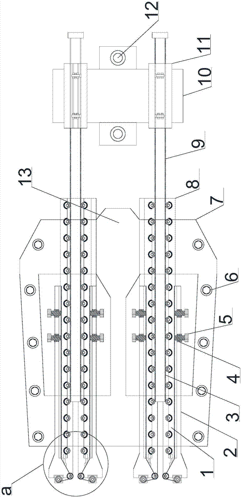
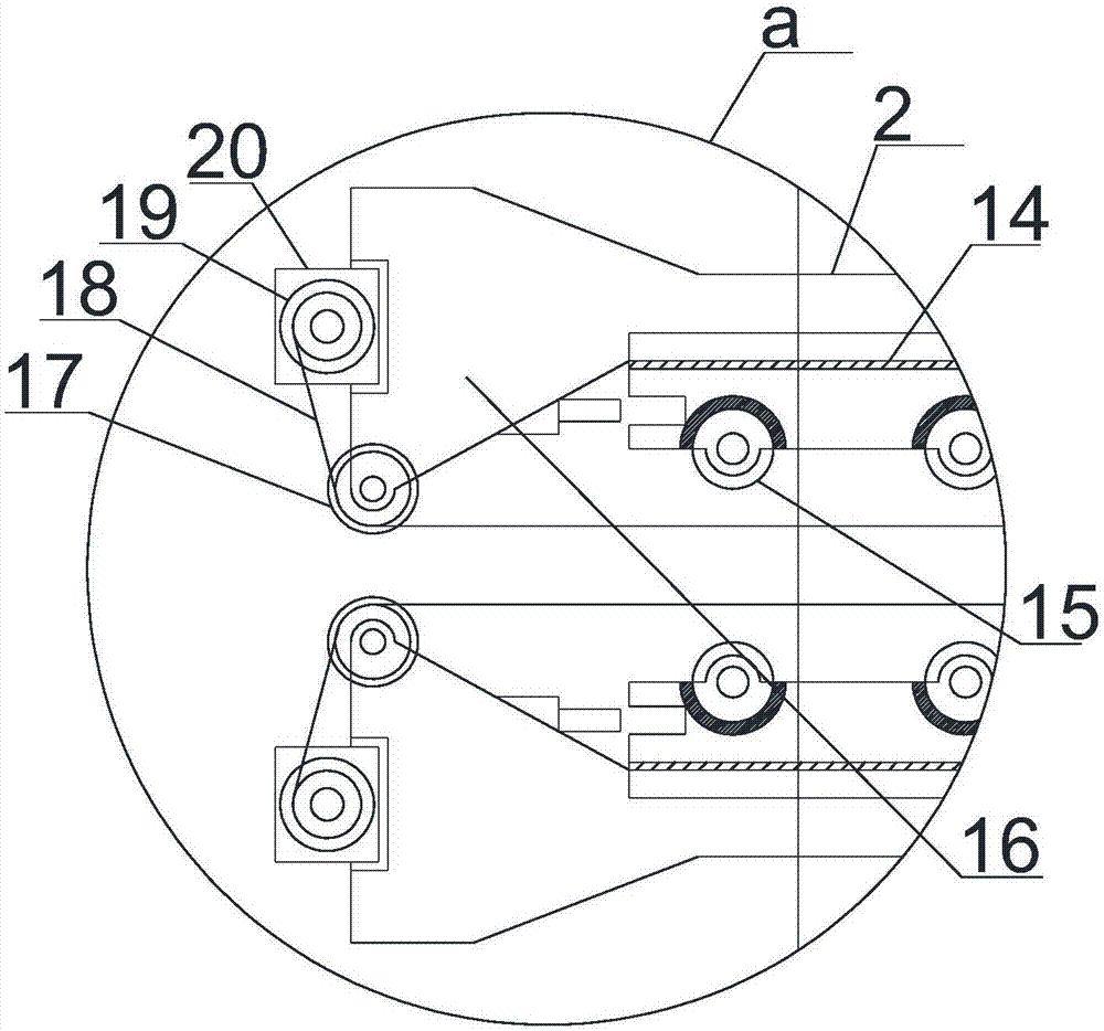
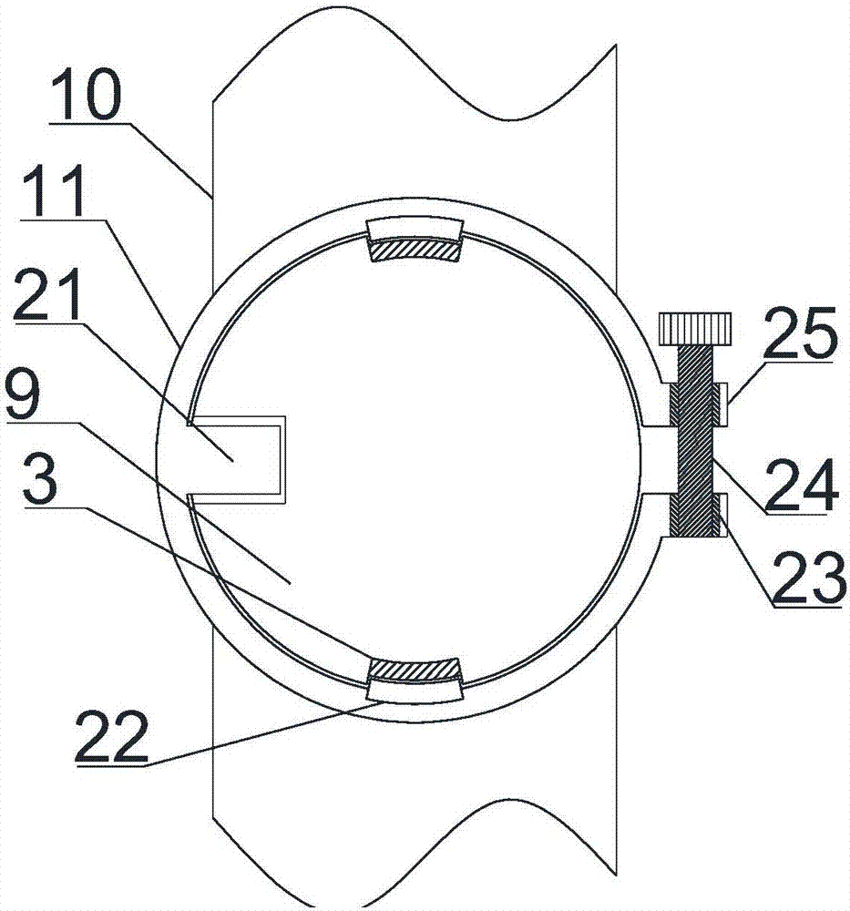
[0018] see Figure 1~3 , in an embodiment of the present invention, a high-rise construction extension cantilever device includes a fixed installation plate 13, and the upper and lower sides of the fixed installation plate 13 are symmetrically provided with fixed installation wing plates 7, and the edge positions are set through hexagonal The screws 6 are fixed, and weight-reducing holes are provided between the fixed installation wing plates 7 and the fixed i...


PUM


Abstract

The invention discloses a high-rise construction cantilever extending device. The high-rise construction cantilever extending device comprises a fixing installing plate. Fixing installing wing plates are symmetrically arranged on the upper side and the lower side of the fixing installing plate. Each fixing installing wing plate is horizontally provided with a limiting telescopic fixing module. Each limiting telescopic fixing module comprises a limiting telescopic drum horizontally installed on the corresponding fixing installing wing plate. A limiting telescopic hole is horizontally and coaxially formed in the each limiting telescopic drum. A telescopic supporting sliding rod is arranged in each limiting telescopic hole in a penetrating mode. Telescopic pulleys are evenly and symmetrically arranged on the upper side and the lower side of the interior of each limiting telescopic hole at equal intervals in an embedded mode. Limiting telescopic wheel grooves matched with the telescopic pulleys are horizontally arranged on the upper side and the lower side of the interior of each limiting telescopic sliding rod. The outer side of the left half section of each limiting telescopic drum is slidably provided with a positioning telescopic drum. The high-rise construction cantilever extending device has the advantages of being novel in structural design, efficient and stable in transmission, simple, fast and convenient to install, small in size, high in strength, and operation environent construction is achieved.

Description

technical field [0001] The invention relates to a construction machine, in particular to an extended cantilever device for high-rise construction. Background technique [0002] With the development of society and the improvement of people's living standards, in order to alleviate the housing problems caused by dense population, high-rise buildings have been built. Cantilever devices are often used in the later construction of high-rise buildings. However, the cantilever devices currently used are not suitable for structural design. Science, resulting in problems such as uneven force, large devices, etc., seriously restricting its use and development in this field. [0003] In order to solve the above problems, the present invention is proposed, which overcomes the current cantilever device. Due to the design of the diagonal stay rod, the size requirements of the diagonal stay rod are high, and the weighing range is small, resulting in long installation time during installati...

Claims


Application Information

Patent Timeline
IPC IPC(8): E04G3/18E04G5/04
CPCE04G3/18E04G5/04
Inventor 梁静
Owner ZHENGZHOU UNIV
Features
  • Generate Ideas
  • Intellectual Property
  • Life Sciences
  • Materials
  • Tech Scout
  • Unparalleled Data Quality
  • Higher Quality Content
  • 60% Fewer Hallucinations
Learn More