
A hydraulic buckle

An undercut device and hydraulic technology, applied in wellbore/well components, earthwork drilling and production, etc., can solve the problems of small application range, large energy loss, small output torque, etc., and achieve convenient operation, large output torque, and reduced friction The effect of loss

Active Publication Date: 2018-08-10
山东科瑞石油装备有限公司
View PDF8 Cites 1 Cited by
  • Summary
  • Abstract
  • Description
  • Claims
  • Application Information

AI Technical Summary

Problems solved by technology

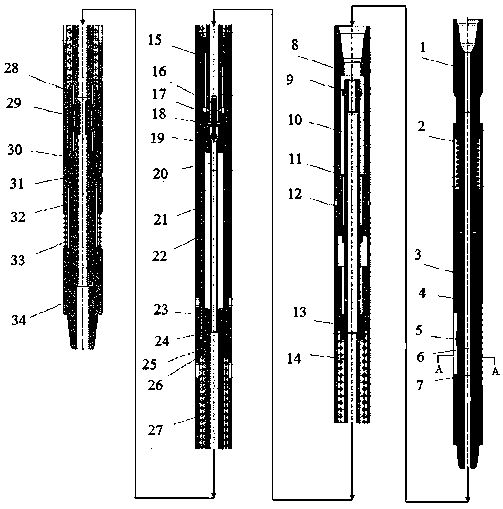
[0004] The purpose of the present invention is to solve the shortcomings of the above-mentioned prior art, realize the undercutting operation through the bottom reversal of the hydraulic drive tool, and solve the large energy loss and small output torque of ordinary undercutting tools in the process of using on site , small application range, complex operation, etc., and can meet the needs of undercut operations in highly deviated wells and horizontal wells

Method used


Image

  • A hydraulic buckle
  • A hydraulic buckle
  • A hydraulic buckle

Examples


Embodiment Construction

[0031]In order to make the purpose, technical solutions and advantages of the embodiments of the present invention clearer, the technical solutions in the embodiments of the present invention will be clearly and completely described below in conjunction with the drawings in the embodiments of the present invention. Obviously, the described embodiments It is a part of embodiments of the present invention, but not all embodiments. The components of the embodiments of the invention generally described and illustrated in the figures herein may be arranged and designed in a variety of different configurations. Accordingly, the following detailed description of the embodiments of the invention provided in the accompanying drawings is not intended to limit the scope of the claimed invention, but merely represents selected embodiments of the invention. Based on the embodiments of the present invention, all other embodiments obtained by persons of ordinary skill in the art without maki...


PUM


Abstract

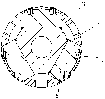
The invention discloses a novel hydraulic back-off device comprising an anchoring device, a pressurizing device, a power transmission device and a power output device. The pressurizing device used for increasing the pressure is arranged on the lower portion of the anchoring device. The power transmission device used for power transmission is arranged on the lower portion of the pressurizing device. The power output device for outputting the hydraulic pressure is arranged on the lower portion of the power transmission device. Compared with the prior art, hydraulic drive is adopted as driving force; an axial power shaft, a quick-replacement drive head and a rotating power shaft are taken as a main power actuator; the axial power shaft and the quick-replacement drive head are of a split type structure so that parts can be machined, replaced and maintained easily; a double ratchet set is designed for power output, an inner ratchet and an outer ratchet are mutually independent, the inner ratchet is not affected by the lower rotary torque, and the outer ratchet guarantees that rotating of the back-off torque is avoided, so that reliable and safe operation of the tool is guaranteed, the output torque is large, and operation is easy.

Description

technical field [0001] The invention relates to the field of oil exploitation equipment, in particular to a hydraulic undercut tool for highly deviated wells and horizontal wells. Background technique [0002] In recent years, with the rapid development of my country's economy and the continuous attenuation of oil and gas field development and non-renewable resources, in order to alleviate the situation that my country's oil and gas resources are overly dependent on imports, major domestic oil fields have accelerated the exploration and development of oil and gas resources. The development process of oil and gas wells In the middle, especially in the late stage of oil well production, it is necessary to implement production stimulation measures. During the process of drilling workover / production stimulation measures, pipe string jamming accidents often occur. Once a stuck accident occurs, it will be very troublesome to deal with, which will increase the operation cycle and co...

Claims


Application Information

Patent Timeline
Patent Type & Authority Patents(China)
IPC IPC(8): E21B23/08
CPCE21B23/08
Inventor 刘化国陈志强张代明贺勇付传红王金乐刘凯泉
Owner 山东科瑞石油装备有限公司
Learn More