
Double-way mechanical seal ring

A mechanical seal and sealing ring technology, applied in the direction of engine seals, mechanical equipment, engine components, etc., can solve the problems of insufficient opening force of the end face, insufficient rotation selectivity, poor anti-interference performance, etc. The effect of simple structure design and high rigidity of air film

Inactive Publication Date: 2017-12-19
CHONGQING THREE GORGES UNIV
View PDF13 Cites 10 Cited by
  • Summary
  • Abstract
  • Description
  • Claims
  • Application Information

AI Technical Summary

Problems solved by technology

However, the existing non-contact mechanical seals that can rotate in both directions still generally have problems such as insufficient opening force of the end face, large leakage, complicated manufacturing, poor anti-interference performance, and insufficient rotation selectivity.

Method used

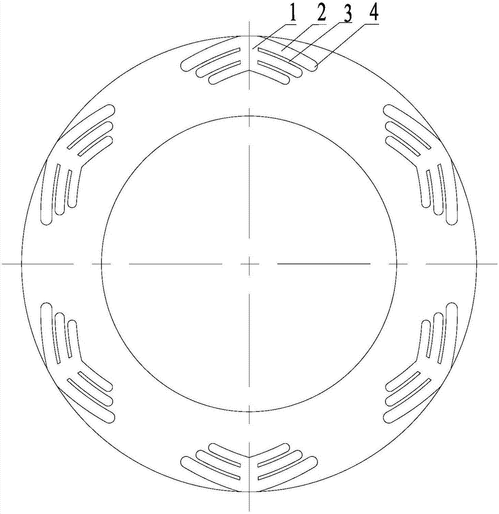

Image

  • Double-way mechanical seal ring
  • Double-way mechanical seal ring
  • Double-way mechanical seal ring

Examples


Embodiment 1

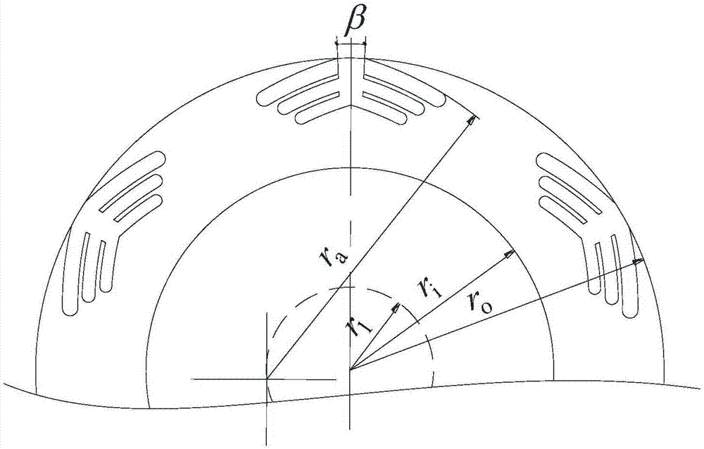
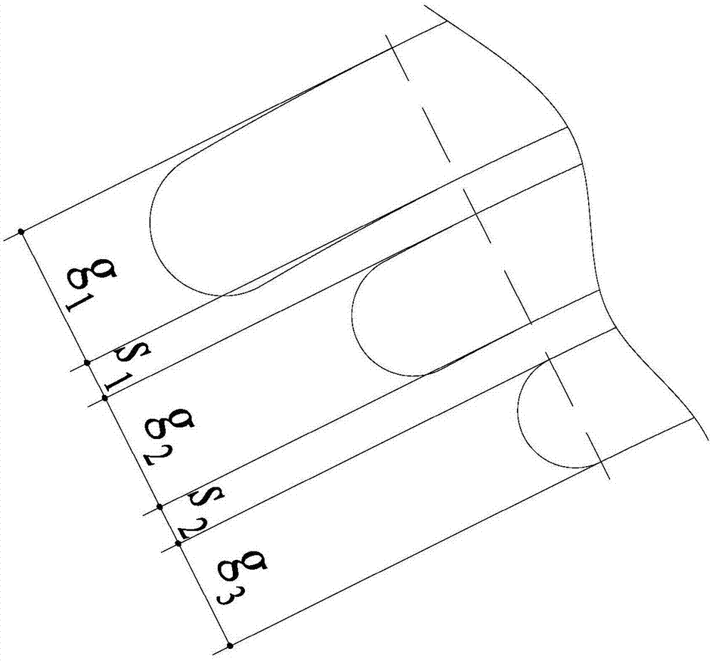
[0042] As attached to the manual figure 1 , 2 As shown in and 3, a two-way mechanical seal ring includes two seal rings of the mechanical seal, that is, a moving ring and a static ring; the end face of the moving ring is provided with six imitation finger-shaped grooves evenly distributed in the circumferential direction; each imitation The finger-shaped grooves are composed of an air inlet groove 1 distributed radially along the sealing ring, and left and right finger-shaped grooves 2 respectively connected to both sides of the air inlet groove 1; the air inlet groove 1 is composed of two air inlet grooves distributed radially along the sealing ring The straight line is composed of a straight line, and the extension line of the straight line inward passes through the rotary shaft of the seal ring, and the extension line of the straight line passes through the intersection of the outermost side of the finger groove 2 and the outer circle of the seal ring; the left and right fi...

Embodiment 2

[0051] As attached to the manual Figure 4 As shown, the difference between the two-way mechanical seal ring described in Example 2 and the two-way mechanical seal ring described in Example 1 is that the end surface of the moving ring is provided with eight finger-like grooves evenly distributed in the circumferential direction; In each finger-like groove, there are two rows of left and right finger-shaped grooves 2, which are distributed along the radial direction of the sealing ring, and are symmetrical about the central axis of the air inlet groove 1; The grooves 2 are separated by an ungrooved sealing weir 4; the radius r of the outer circle of the sealing ring o =80mm, the radius r of the inner hole of the sealing ring i =55mm; the groove depths of all finger-shaped grooves in each finger-shaped groove are equal, and the groove depth is 5 μm; the angle β between the two straight lines forming the air inlet groove is 8°; for the same finger-shaped groove, the same The ar...

Embodiment 3

[0057] As attached to the manual Figure 5 As shown, the difference between the two-way mechanical seal ring described in Embodiment 3 and the two-way mechanical seal ring described in Embodiment 1 is that the end surface of the moving ring is provided with seven finger-like grooves evenly distributed in the circumferential direction; In each finger-like groove, there are three rows of left and right finger-shaped grooves 2, all distributed along the radial direction of the sealing ring, and the left and right finger-shaped grooves 2 are asymmetrical; the left and right finger-shaped grooves 2 are asymmetrical, specifically shown as a The depth of the side groove is 5 μm, and the arc length is 19.5-24.5 mm (main groove), and the depth of the groove on the other side is 3 μm, and the arc length is 7.5-15.5 mm (protective groove).

[0058] In the process of applying the two-way mechanical seal ring described in this example, during normal operation, when the direction of rotatio...


PUM

PropertyMeasurementUnit
Thicknessaaaaaaaaaa

Abstract

The invention relates to a double-way mechanical seal ring. The double-way mechanical seal ring comprises two mechanical seal ring bodies, that is a moving ring body and a stationary ring body. The double-way mechanical seal ring is characterized in that the end face of at least one seal ring body is provided with a plurality of finger imitating type grooves; each finger imitating type groove is composed of an air inlet groove which is distributed in the radial direction of the corresponding seal ring body, left finger-shaped grooves and right finger-shaped grooves, and the left finger-shaped grooves and the right finger-shaped grooves communicate with the two sides of the air inlet groove correspondingly; each air inlet groove is composed of two straight lines which are distributed in the radial direction of the corresponding seal ring body, inward extending lines of the straight lines pass through a rotary shaft of the corresponding seal ring body, and outward extending lines of the straight lines pass through the intersection points of the outermost sides of the finger-shaped grooves and an outer circle of the corresponding seal ring body; the left finger-shaped grooves and the right finger-shaped grooves are each composed of two concentric circular arcs and a semi-circular arc which is located at the tail end of the corresponding finger-shaped groove; and the two circular arcs, located on the innermost side in the radial direction of the corresponding seal ring body, of one left finger-shaped groove and one right finger-shaped groove are directly connected with each other. The double-way mechanical seal ring has the numerous advantages that the end face opening force is large, the leakage rate is low, the rigidity of an air film is high, the friction power loss is small, operation is stable, and the service life is long.

Description

technical field [0001] The invention belongs to the technical field of fluid mechanical end face sealing, and relates to a bidirectionally rotatable mechanical sealing device, in particular to a bidirectional mechanical sealing ring. Background technique [0002] At present, non-contact mechanical seals are more and more widely used in rotating machinery such as centrifugal compressors, pumps, and centrifuges due to their advantages such as low power consumption, low leakage, low wear, and stable performance. Existing mechanical seals that can rotate in both directions, such as Chinese patents CN104265900A "bidirectionally rotating gas dynamic and static pressure mechanical seal imitating bird wing-shaped groove structure", CN104165228A "a kind of mimosa-like hole cluster end face mechanical seal structure", CN103133697A "Bidirectionally rotatable dovetail groove end face mechanical seal structure", CN101469771 "a two-way rotatable stepped arc groove mechanical seal end face...

Claims


Application Information

Patent Timeline
IPC IPC(8): F16J15/34
CPCF16J15/34F16J15/3412
Inventor 产文曹晓龙蒋德敏崔政王文涛王利锋李轩直
Owner CHONGQING THREE GORGES UNIV
Learn More