
A method for setting chip working mode

A working mode and chip technology, applied in the direction of logic circuit interface device, logic circuit connection/interface layout, etc., can solve the problem of inability to meet the needs of use, and achieve the effect of saving chip pins, simplifying application circuits, and reducing costs

Active Publication Date: 2021-11-26
钰泰半导体股份有限公司
View PDF5 Cites 0 Cited by
  • Summary
  • Abstract
  • Description
  • Claims
  • Application Information

AI Technical Summary

Problems solved by technology

[0004] It can be seen that the existing working mode setting method of chips with multiple working modes can no longer meet the needs of use. For this reason, it is necessary to develop a new method that can utilize simple circuits to set the required working modes of supporting products to meet the requirements. make demand

Method used


Image

  • A method for setting chip working mode
  • A method for setting chip working mode
  • A method for setting chip working mode

Examples


Embodiment Construction

[0020] Below in conjunction with the drawings, preferred embodiments of the present invention are given and described in detail.

[0021] see Figure 1-24 ,; The present invention, that is, a method for setting a chip working mode, comprises the following steps:

[0022] Step S1 is implemented in any of the following ways:

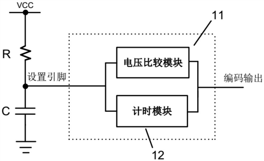
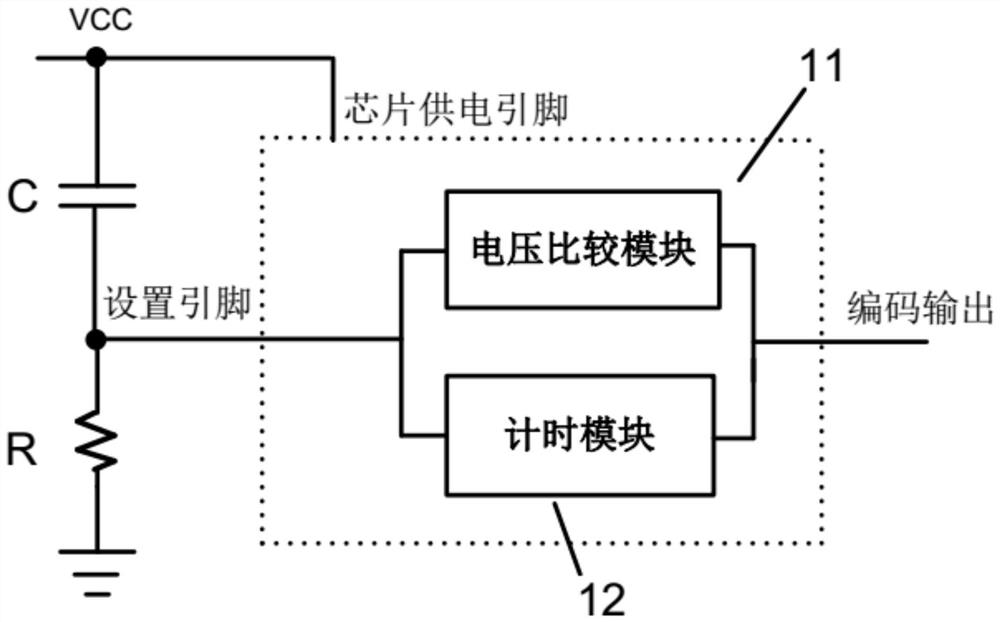
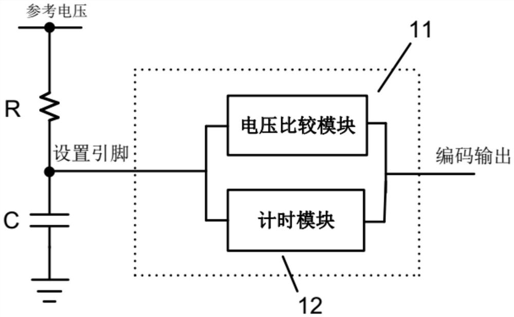
[0023] (1) Connect a resistor R to the constant voltage source (for example: power supply voltage VCC, reference voltage, etc.) or ground (or reference voltage ground) on the setting pin of the chip, and connect a capacitor C (or reference voltage ground) To ground or to a constant voltage source (for example: power supply voltage VCC, reference voltage, etc.) (specifically, it can be as Figure 1-6 shown);

[0024] (2) Connect a resistor R to the constant voltage source (for example: power supply voltage VCC, reference voltage, etc.) or to ground (or reference voltage ground) on the setting pin of the chip, and build a capacitor C to ground (or referenc...


PUM


Abstract

The present invention relates to a method for setting the working mode of a chip, which includes the following steps: Step S1, which is realized in any of the following ways: (1) A resistor is connected to a constant voltage source or ground on the setting pin of the chip, and Connect an external capacitor to the ground or to the constant voltage source; (2) Connect a resistor to the constant voltage source or to the ground on the setting pin of the chip, and a built-in capacitor to the ground or to the constant voltage source; (3) Connect to the chip’s setting pin Set an external capacitor to the ground or to a constant voltage source on the setting pin, and a built-in resistor to the constant voltage source or to the ground; (4) Connect a capacitor to the ground or to the constant voltage source on the setting pin of the chip, and a built-in The constant current source charges or discharges the capacitor; step S2, detects and obtains the corresponding working mode code according to the rising rate or falling rate of the voltage of the capacitor, so as to determine the working mode corresponding to the working mode code. The invention saves the total number of pins of the chip, reduces the cost, improves the integration degree of the chip, and simplifies the application circuit.

Description

technical field [0001] The invention relates to an integrated circuit, in particular to a method for setting a chip working mode. Background technique [0002] In today's society, mobile digital products such as smartphones, smart wearables, and tablet computers are booming. With the increase in the functions of mobile digital products, the high power consumption of multimedia applications, and the battery life are far behind the rhythm of the times. Therefore, there has been a portable power supply that can charge and supply power to all digital products, that is, a mobile power supply. With the development of mobile power in recent years, the products are becoming more and more diversified. Emerging technologies are mainly developed in wireless charging and solar thin-film batteries. It is hoped that there will be a major breakthrough in conversion efficiency in the near future. Products are developing towards lightness and multi-functionality, and the variety of digital ...

Claims


Application Information

Patent Timeline
Patent Type & Authority Patents(China)
IPC IPC(8): H03K19/0175
CPCH03K19/017509
Inventor 张征胡央维江辉华丁德彬
Owner 钰泰半导体股份有限公司
Learn More