a soy milk machine

A soymilk machine and machine head technology, applied in kitchen utensils, home utensils, beverage preparation devices, etc., can solve the problems of not beautiful appearance, unfavorable cleaning, easy storage of slag, etc., and achieve easy cleaning, convenient cleaning, reliability and stability. Sex-enhancing effect

Active Publication Date: 2020-04-10
JOYOUNG CO LTD
View PDF10 Cites 0 Cited by
  • Summary
  • Abstract
  • Description
  • Claims
  • Application Information

AI Technical Summary

Problems solved by technology

Since the anti-overflow electrode rod is placed abruptly on the machine head, the appearance is not beautiful enough, and after the pulping is completed, the connection between the anti-overflow electrode rod and the machine head is easy to collect slag and dirt, which is not conducive to cleaning

Method used


Image

  • a soy milk machine
  • a soy milk machine
  • a soy milk machine

Examples


Embodiment 1

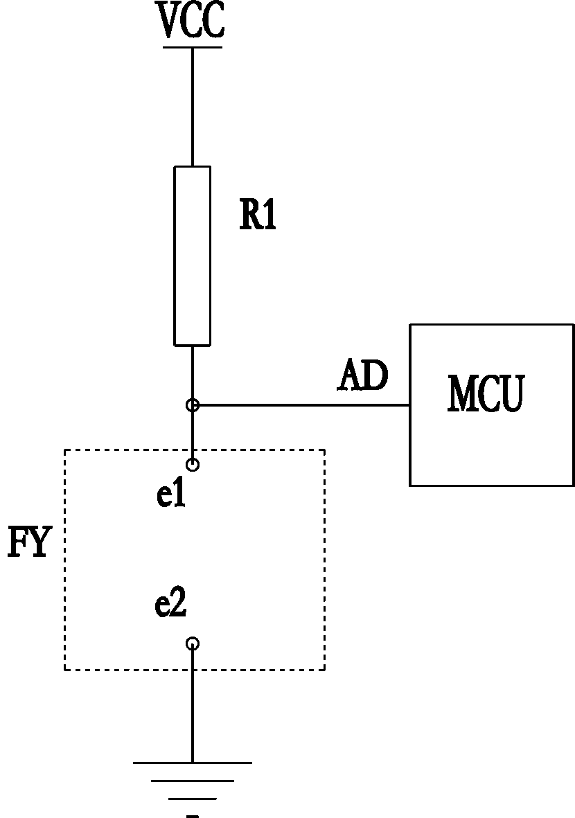
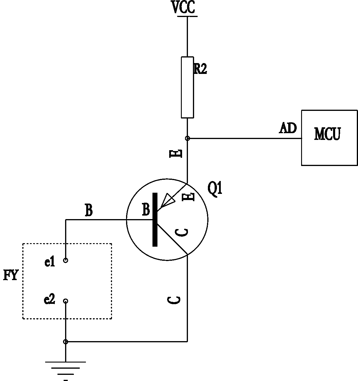
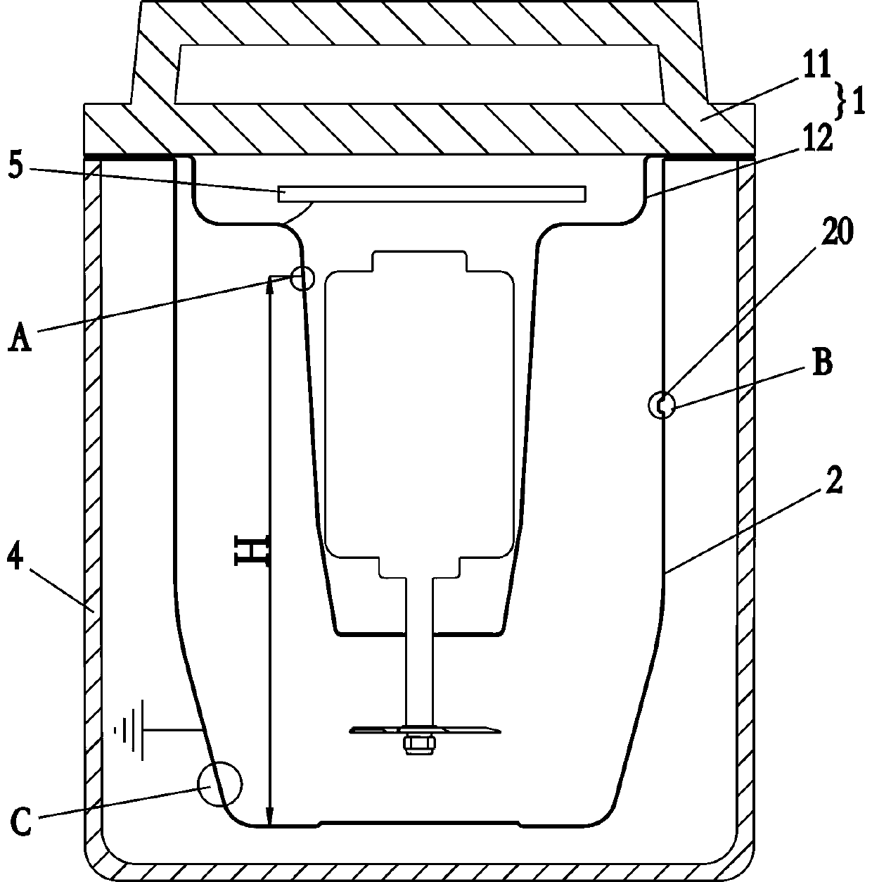
[0035] Such as image 3 , Figure 4 , Figure 5 , Image 6 Shown is a schematic structural diagram of the first embodiment of the present invention. A soymilk machine, comprising a machine head 1 and a cup body, the machine head 1 comprising a machine head upper cover 11 and a metal lower cover 12, the machine head has no anti-overflow electrode rod, and the cup body is provided with a water level indicator Line 20, the outer wall of the lower metal cover 12 has a first covering area 121 covered by an insulating non-stick coating and a first hollow area not covered by the insulating non-stick coating. The first hollow area is located at the water level marking line Above 20, the first hollow area forms an anti-overflow detection electrode, the cup body is provided with a conductive electrode, the conductive electrode is located below the water level marking line 20, the slurry rises to connect the conductive electrode with the anti-overflow detection electrode, Realize the dete...

Embodiment 2

[0050] Such as Figure 7 , Figure 8 Shown is a schematic structural diagram of the second embodiment of the present invention. The difference between this embodiment and the first embodiment is that: in this embodiment, the bottom wall of the metal cup 2 is provided with a through hole 23, and the conductive electrode passes through the through hole 23 and is exposed to the conductive inside the metal cup 2. The column 3 is a sealed fit between the conductive column 3 and the through hole 23.

[0051] In this embodiment, the conductive column 3 includes a top brim 31 and a connecting column 32 integral with the hat brim 31. The bottom of the brim 31 has an annular groove 33 arranged around the connecting column 32. The connecting column A sealing ring 6 is sleeved on 32, and the sealing ring 6 is clamped in the annular groove 33 by the brim 31 and the bottom wall of the metal cup body 2. At the same time, an annular clamping groove 60 is provided on the outer side of the middle...


PUM


Abstract

The invention relates to a small kitchen electrical appliance and especially relates to a soybean milk machine. The machine comprises a machine head and a cup body, wherein the machine head comprises a machine head upper cover and a metal lower cover. The machine is characterized in that an anti-overflowing electrode rod is not disposed on the machine head; a water level identification line is disposed on the cup body; a first coating area coated by an insulated non-sticky coating and a first hollow area which is not coated by the insulated non-sticky layer are disposed on the outer wall of the metal lower cover; the first hollow area is located above the water level identification line; an anti-overflowing detection pole is formed by the first hollow area; an electric conduction pole is disposed on the cup body; the electric conduction pole is located under the water level identification line; and when soybean milk ascends, the electric conduction pole can communicate with the anti-overflowing detection pole, so anti-overflowing signals can be detected. Through application of the technical scheme, no anti-overflowing electrode rod is disposed on the soybean milk machine head, so the whole machine can be cleaned more easily; the anti-overflowing signals can be detected reliably and stably by the soybean milk machine; and plus, in comparison with the prior art, soybean milk adhesion does not take place to the soybean milk machine provided by the invention.

Description

Technical field [0001] The invention relates to a small kitchen appliance, in particular to a soybean milk machine. Background technique [0002] The existing soymilk machine includes a machine head and a cup body. The machine head includes a machine head upper cover and a metal lower cover. A heating tube is arranged on the cup body to heat the cup body during the pulping process. During the cooking and heating process, because the motor is installed in the metal lower cover, the motor will release a large amount of heat during high-speed operation, and the metal lower cover will absorb the heat generated by the motor due to its good heat transfer performance. The outer wall of the metal lower cover is hot. When the particles in the slurry contact the outer wall of the hot metal lower cover, scorching will occur. Especially after the beverage is made without being soaked in cold water, the machine head is particularly difficult to clean. Cleaning up is easy to breed bacteria. T...

Claims


Application Information

Patent Timeline
Patent Type & Authority Patents(China)
IPC IPC(8): A47J31/00A47J31/44A47J43/044
CPCA47J31/00A47J31/4403A47J43/044
Inventor 王旭宁刘爽章佳锋薛领珑
Owner JOYOUNG CO LTD
Why Eureka
Try Eureka