Dust absorbing and treating device for building site

A technology for construction sites and treatment devices, which is applied in the directions of combination devices, smoke and dust removal, cleaning methods and utensils, etc., can solve the problems of decreased filtration efficiency, high use cost, and muddy ground, and achieves reduction of air dust content and simple structure. , easy to use effect

Inactive Publication Date: 2017-12-22
陆春土
View PDF1 Cites 16 Cited by
  • Summary
  • Abstract
  • Description
  • Claims
  • Application Information

AI Technical Summary

Problems solved by technology

[0003] However, the dust reduction schemes used in construction sites are generally sprinkling water on a large area, and the vehicles are sprayed and cleaned with water. The main method is to use the spray water to absorb the floating dust in the air to achieve the effect of dust reduction. There is too much water in the ground area of ​​the site, which makes the ground muddy and difficult to walk, which will have a certain impact on the construction; moreover, a large amount of spray water is required for spraying during the dust reduction process, which will cause waste of water resources, even the commonly used dust reduction fog gun device, will cause a waste of water resources
Nowadays, small-scale dust collectors generally use cloth bags or electrostatic dust collectors. If they are used in a scene with a large head, the small bag dust collectors consume too quickly and require frequent replacement of filter elements. The pressure loss is large, and the filtration efficiency is significantly reduced; and the small electrostatic precipitator has a complex structure, high maintenance and use costs, and is not suitable for filtering large-sized dust
[0004] For this reason Chinese patent (authorized announcement: CN206483245U) discloses a kind of construction site temporary dust suppression device, but the dust removal effect of this device is still not good

Method used


Image

  • Dust absorbing and treating device for building site
  • Dust absorbing and treating device for building site
  • Dust absorbing and treating device for building site

Examples


Embodiment Construction

[0021] The technical solution of this patent will be further described in detail below in conjunction with specific embodiments.

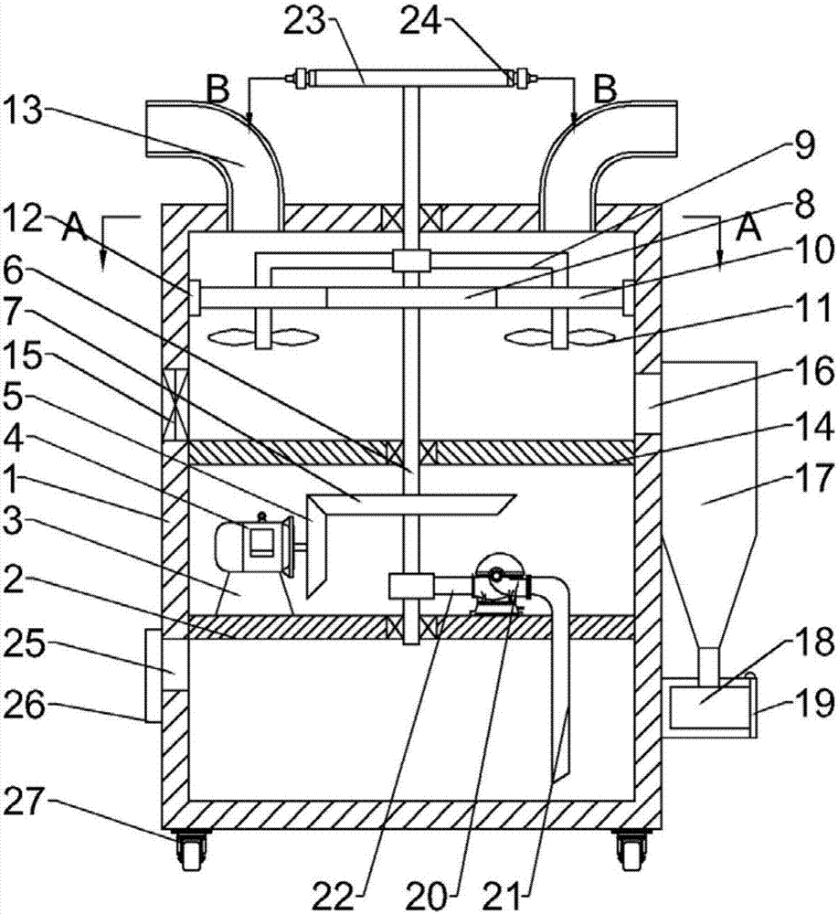
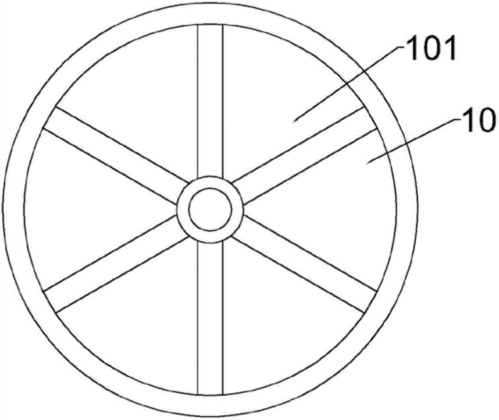
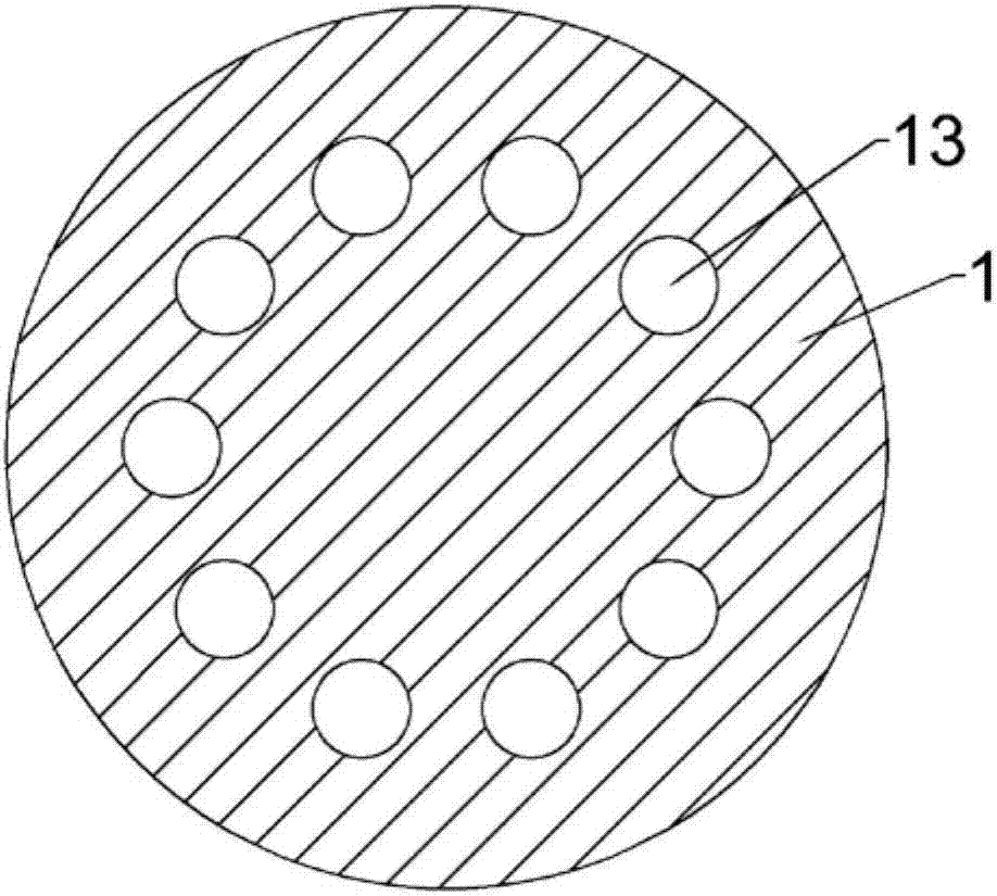
[0022] see Figure 1-4 , a dust absorbing and processing device for a construction site, comprising a housing 1, a lower partition 2 is fixedly connected to the lower part of the housing 1, and a motor base 3 is fixedly connected to the left side above the lower partition 2, and the motor base 3 A motor 4 is fixedly connected to the top, and the output end of the motor 4 is fixedly connected to a driving bevel gear 5. The middle part above the lower partition 2 is connected to a longitudinal rotation shaft 6 through bearing rotation. The longitudinal rotation shaft 6 is a tubular structure, and the longitudinal rotation shaft 6 is fixedly connected with a driven bevel gear 7 below, and the driven bevel gear 7 is meshed with the driving bevel gear 5. The outer side of the longitudinal rotation shaft 6 is fixedly connected with a driving gear 8, and ...


PUM

PropertyMeasurementUnit
particle diameteraaaaaaaaaa

Abstract

The invention discloses a dust absorbing and treating device for a building site. The dust absorbing and treating device comprises a shell, a lower partition is fixedly connected below the inside of the shell, a motor seat is fixedly connected on the left side above the lower partition, a motor is fixedly connected above the motor seat, an output end of the motor is fixedly connected with a driving bevel gear, a longitudinal rotating shaft is rotatably connected in the middle above the lower partition through bearing and is of a tubular structure, a driven bevel gear is fixedly connected below the longitudinal rotating shaft, and the driven bevel gear and the driving bevel gear are meshed. Compared with the prior art, the dust absorbing and treating device has the advantages that the device is simple in structure and convenient to use; through omnibearing dust absorbing, dust in each direction of the device can be absorbed more cleanly; the device combines two modes of dust collection for convenience of treatment with water spraying to lower dust content in air, so that environment of the building site is better, and the device is worthy of popularization.

Description

technical field [0001] The invention relates to a dust removal device, in particular to a dust absorption and treatment device for a construction site. Background technique [0002] In the demolition of old buildings, whether it is manual demolition or directional blasting, dust pollution is often caused, especially in the weather with high wind and dry objects, the dust pollution is more prominent. The main sources of dust in building construction are: excavation and removal of muck, backfill, exposed material piles, garbage thrown from top to bottom during demolition construction, piled construction waste, muck removal and on-site mixing of concrete Wait. Flying dust includes three components: falling dust (particle size >100 μm), floating dust (particle size 10-100 μm), and inhalable particulate matter (particle size <10 μm). Flying dust pollution is one of the most important pollutants in the air, and it has become the primary air pollutant in most areas of our c...

Claims


Application Information

Patent Timeline
Patent Type & Authority Applications(China)
IPC IPC(8): B01D50/00B08B15/00
CPCB08B15/00B01D50/40
Inventor 陆春土
Owner 陆春土
Why Eureka
Try Eureka