
Height adjustable de-ironing separator used for building

A construction and iron remover technology, applied in chemical instruments and methods, magnetic separation, cleaning devices, etc., can solve the problems of crushing equipment damage, regular manual cleaning, limited effect, etc., to ensure the adsorption effect, ensure cleanliness, improve The effect of iron removal effect

Inactive Publication Date: 2017-12-22
DONGGUAN LIANZHOU INTPROP OPERATION MANAGEMENT CO LTD
View PDF3 Cites 3 Cited by
  • Summary
  • Abstract
  • Description
  • Claims
  • Application Information

AI Technical Summary

Problems solved by technology

[0002] There are many iron metal parts mixed in the existing construction waste, and such metal parts will cause damage to the crushing equipment when the construction waste is crushed, and such metal parts and other stone waste need to be sorted. They cannot be processed together, so the existing method is to remove iron through the iron remover, and the existing iron remover is generally provided with a rib on the conveyor belt, so that the ferrous metal can fall along the rib, however, the lower Falling behind, there is still dust or particles of iron powder on the conveyor belt. After a long time, too much impurities and dust are easy to accumulate on the conveyor belt, which will affect the adsorption effect of the electromagnet. It needs to be cleaned manually regularly, which is very troublesome.
[0003] Moreover, the sidewall is set on the conveyor belt, which only has the direction of auxiliary guiding iron metal falling, and the effect is limited.

Method used


Image

  • Height adjustable de-ironing separator used for building
  • Height adjustable de-ironing separator used for building
  • Height adjustable de-ironing separator used for building

Examples


Embodiment Construction

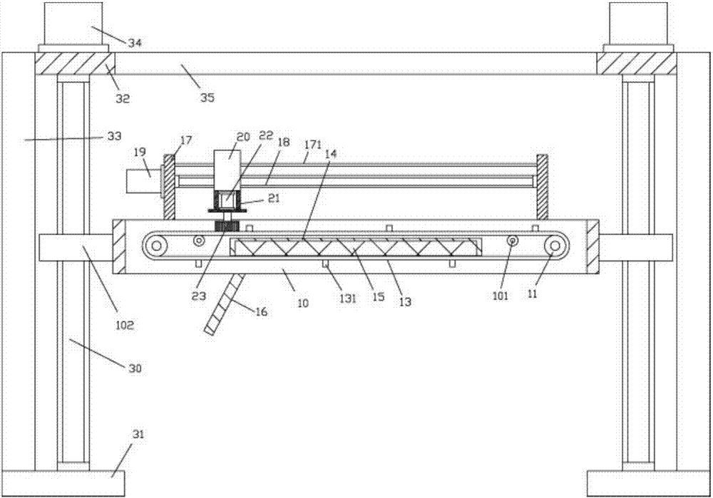
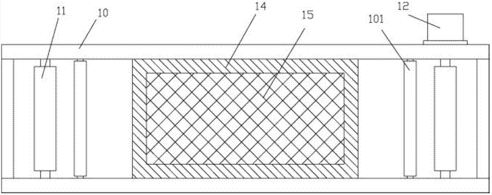
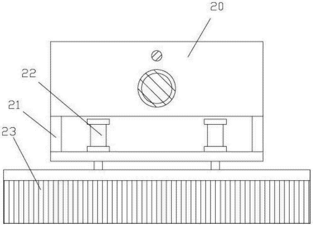
[0018] Examples, see e.g. Figure 1 to Figure 3 As shown, a height-adjustable iron remover for construction includes a main casing 10. The main casing 10 is a rectangular frame body. An adjusting block 102 is fixed on the outer side walls of the left and right side panels of the main casing 10. The adjusting block 102 is screwed. Connected to the corresponding vertical screw 30, the bottom of the vertical screw 30 is hinged on the lower base 31, the top of the vertical screw 30 is hinged on the bottom of the upper plate 32, two lower bases 31 are fixed with side vertical Plate 33, the top of side vertical plate 33 is fixed on the upper plate body 32, and the top surface both sides of upper plate body 32 is fixed with lifting motor 34, and the output shaft of lifting motor 34 is a spline shaft, and the spline shaft is inserted in In the spline hole that the top of the vertical screw rod 30 has;

[0019] The two sides of the main casing 10 are provided with transmission rollers...


PUM


Abstract

The invention discloses a height-adjustable iron remover for buildings, which includes a main casing, the main casing is a rectangular frame body, and adjustment blocks are fixed on the outer walls of the left and right side panels of the main casing, and the adjustment blocks are screwed to the corresponding In the vertical screw rod, the bottom end of the vertical screw rod is hinged on the lower base plate, the top end of the vertical screw rod is hinged on the bottom surface of the upper plate body, side vertical plates are fixed on the two lower base plates, and the top ends of the side vertical plates are fixed on On the upper plate body, a lifting motor is fixed on both sides of the top surface of the upper plate body, the output shaft of the lifting motor is a spline shaft, and the spline shaft is inserted and sleeved in the spline hole provided on the top of the vertical screw rod. The present invention can adjust the main casing up and down according to the height of the lower conveyor frame, so as to ensure that the conveyor belt is close to the building sundries conveyed on the lower conveyor frame, thereby improving the effect of iron removal, and the conveyor belt can be cleaned by the upper brush It is very convenient to carry out automatic cleaning to ensure its cleanliness, thereby ensuring the adsorption effect of the electromagnet block.

Description

Technical field: [0001] The invention relates to the technical field of construction equipment, in particular to a height-adjustable iron remover for construction. Background technique: [0002] There are many iron metal parts mixed in the existing construction waste, and such metal parts will cause damage to the crushing equipment when the construction waste is crushed, and such metal parts and other stone waste need to be sorted. They cannot be processed together, so the existing method is to remove iron through the iron remover, and the existing iron remover is generally provided with a rib on the conveyor belt, so that the ferrous metal can fall along the rib, however, the lower Backward, there is still dust or particles of iron powder on the conveyor belt. After a long time, too much impurities and dust are easy to accumulate on the conveyor belt, which will affect the adsorption effect of the electromagnet. It needs to be cleaned manually regularly, which is very troub...

Claims


Application Information

Patent Timeline
IPC IPC(8): B03C1/22B65G45/18
CPCB03C1/22B65G45/18
Inventor 赵志豪
Owner DONGGUAN LIANZHOU INTPROP OPERATION MANAGEMENT CO LTD
Learn More