
Powder electromagnetic separator

An electromagnetic and machine-selecting technology, applied in magnetic separation, solid separation, chemical instruments and methods, etc., can solve the problems of poor separation effect and separation efficiency of electromagnetic separators

Inactive Publication Date: 2017-10-10
佛山市高明星诺机械设备有限公司
View PDF12 Cites 6 Cited by
  • Summary
  • Abstract
  • Description
  • Claims
  • Application Information

AI Technical Summary

Problems solved by technology

[0004] In view of the shortcomings of the prior art above, the purpose of the present invention is to provide a powder electromagnetic separator, which aims to solve the technical problems of poor separation effect and separation efficiency of the electromagnetic separator in the prior art

Method used


Image

  • Powder electromagnetic separator
  • Powder electromagnetic separator
  • Powder electromagnetic separator

Examples


Embodiment Construction

[0021] The present invention provides a powder electromagnetic separator. In order to make the purpose, technical solution and effect of the present invention clearer and clearer, the present invention will be further described in detail below with reference to the accompanying drawings and examples. It should be understood that the specific embodiments described here are only used to explain the present invention, not to limit the present invention.

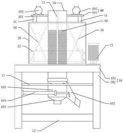
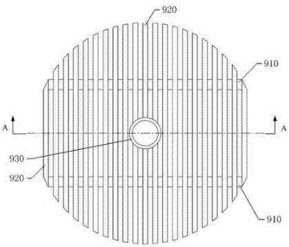
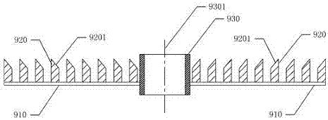
[0022] see Figure 1 to Figure 3 , The invention provides a powder electromagnetic separator. The drawings are only used to explain the structural principle, and are not to scale with the actual product. figure 1 The part indicated by the middle dotted line cannot be directly observed from this viewing angle.

[0023] The powder electromagnetic separator includes a chassis 10, an oil tank 20, a heat exchanger 22 and an oil pump 21 arranged on the chassis, an electromagnetic coil 50 arranged in the oil tank, and an iron removal...


PUM


Abstract

The invention discloses a powder electromagnetic separator, which comprises a bottom frame, an oil tank, a heat exchanger and an oil pump arranged on the bottom frame, an electromagnetic coil arranged in the oil tank, an iron removal cylinder vertically penetrating the oil tank, and an iron removal cylinder arranged in the oil removal tank. The vibration device on the side wall of the iron cylinder, and the unloading device arranged at the bottom of the iron removal cylinder; several pieces of magnetic nets are stacked in the inner cavity of the iron removal cylinder; the oil tank, oil pump and heat exchanger pass through the oil pipe Loop connections. The powder electromagnetic separator provided by the invention improves the iron removal efficiency and quality of the powder, and can effectively remove the heat generated by the electromagnetic coil during operation.

Description

technical field [0001] The invention relates to the technical field of electromagnetic separators, in particular to a powder electromagnetic separator. Background technique [0002] The powder electromagnetic separator is used to remove iron filing impurities in powder materials in ceramics, mining, chemical and other industries. The existing powder electromagnetic separator usually has the disadvantages of high noise and high heat generation, and the separation effect and efficiency are not good, which directly affects the production efficiency and product quality. [0003] It can be seen that the prior art still needs to be improved and enhanced. Contents of the invention [0004] In view of the shortcomings of the prior art above, the purpose of the present invention is to provide an electromagnetic separator for powder materials, which aims to solve the technical problems of poor separation effect and separation efficiency of the electromagnetic separator in the prior...

Claims


Application Information

Patent Timeline
IPC IPC(8): B03C1/02
CPCB03C1/02B03C2201/20
Inventor 梁永权
Owner 佛山市高明星诺机械设备有限公司
Learn More