Method and device for deironing continuously in slurry in bi-twisting mode

A double-rotation, slurry technology, applied in the field of magnetic separation, can solve problems such as complex structure, low iron removal efficiency, difficult maintenance and overhaul, etc., and achieve the goal of improving slurry quality, good iron absorption effect, and good iron removal effect Effect

Inactive Publication Date: 2014-08-13
钟娟英
View PDF6 Cites 9 Cited by
  • Summary
  • Abstract
  • Description
  • Claims
  • Application Information

AI Technical Summary

Problems solved by technology

[0004] 1. The magnetic rod is removed from the slurry bucket repeatedly. During the period of time when it is removed from the slurry bucket, the magnetic rod cannot attract iron to the slurry.
As a result, the intermittent time is longer, the process is interrupted, and the iron removal efficiency is lower, which cannot produce a larger scale effect.
Under the current demand, the existence of the above problems seriously restricts the use and promotion of this type of iron remover
[0005] 2. As the main component, the magnetic rod needs to be moved many times, so the positioning of the motion actuator will be inaccurate and the stability will be affected after long-term service.
And the movement of the magnetic bar is completely controlled by the program and has a relatively complicated structure, which also makes maintenance and repair more difficult

Method used


Image

  • Method and device for deironing continuously in slurry in bi-twisting mode
  • Method and device for deironing continuously in slurry in bi-twisting mode
  • Method and device for deironing continuously in slurry in bi-twisting mode

Examples


Embodiment 1

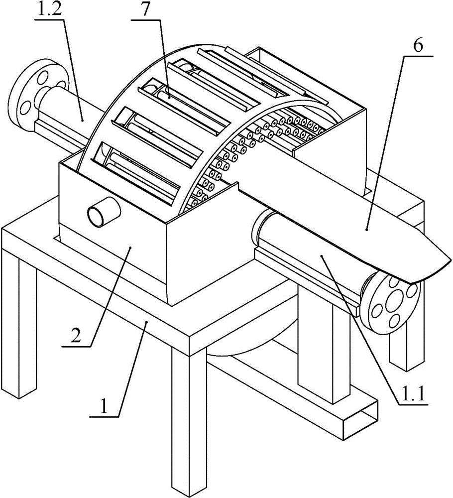
[0050] Such as figure 1 , 2 As shown, the device includes a frame 1, a slurry bucket 2, an inner container 3, a group of magnetic rods 4, an agitator 7 and a rotary water spray device 5. A first fixed frame 1.1 and a second fixed frame 1.2 are respectively installed at positions corresponding to the front and rear of the frame 1 .

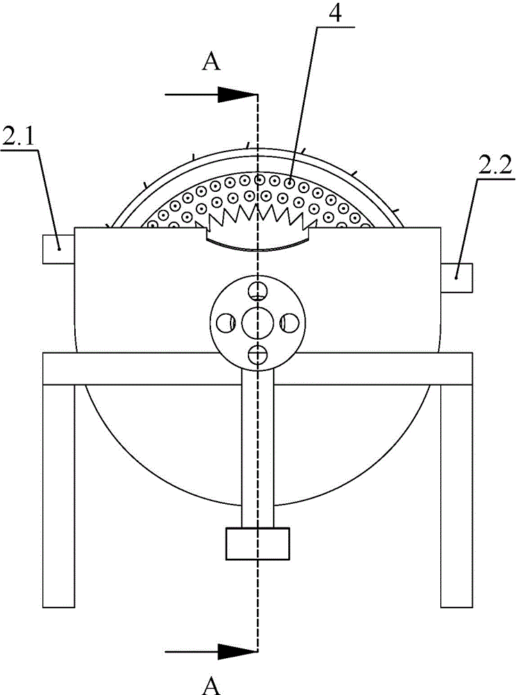
[0051] The slurry bucket 2 is installed on the frame 1, and the bottom of the slurry bucket 2 is an arc structure and the radius of curvature is half of the distance between the left and right side walls. A slurry discharge port 2.2 is opened near the position where the magnetic bar just enters the slurry, and a slurry inlet 2.1 is opened near the position where the magnetic bar just leaves the slurry. And the height of the stock inlet port 2.1 is greater than the height of the stock discharge port 2.2. This ensures that the slurry can be discharged normally.

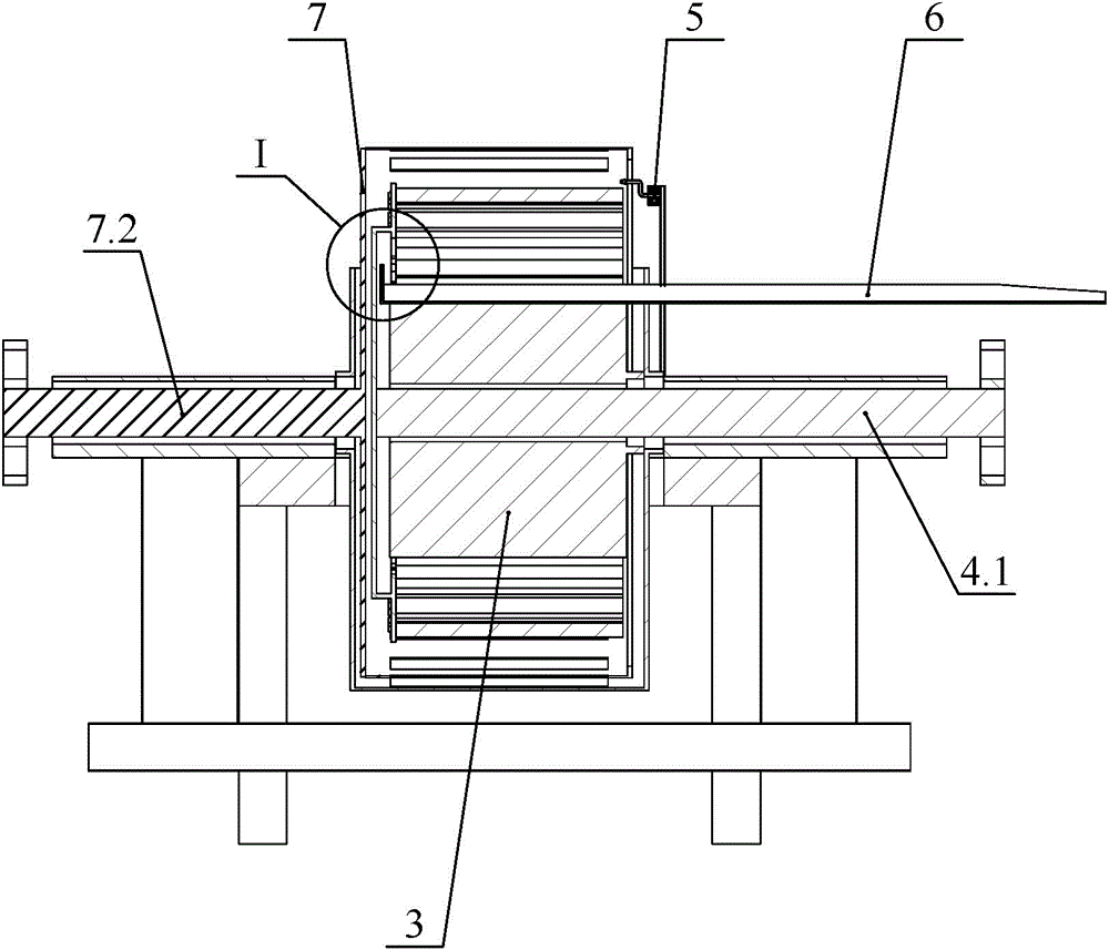
[0052] Such as image 3 , 4 As shown, an inner container 3 is set in the slurry ba...

Embodiment 2

[0063] Compared with Embodiment 1, this embodiment has made changes in the way of removing iron. Such as Figure 7 As shown, in order to remove the iron filings adsorbed on the magnetic rod 4.2 more quickly without scratching the magnetic rod 4.2, high-pressure water flow can also be used for flushing. The rotary water spray device 5 is installed on the frame 1, and the rotary water spray device 5 comprises a shower head 5.1, which can rotate, and the rotary water spray device is positioned at one side of the finger. Therefore, when the magnetic bar group rotates so that the scraper 8 on it just enters the gap between the left finger 9.1 and the right finger 9.2, the arm 9 drives the scraper 8 to move to the front end of the magnetic bar while the nozzle rotates and sprays water. The sprayed water forms a spiral water circle to flush the magnetic bar, and the iron filings absorbed by the magnetic bar and the iron filings on the scraper 8 are washed away. Aiming at the de...


PUM


Abstract

The invention discloses a method and device for deironing continuously in slurry in a bi-twisting mode, and belongs to the field of magnetically separating solids in slurry. Magnetic bars in magnetic bar groups are placed in a slurry barrel for adsorbing scrap iron in slurry, and then the scrap iron adsorbed on the magnetic bars is removed. The method and device for deironing continuously in slurry in a bi-twisting mode are characterized in that the magnetic bars in the magnetic bar groups are arranged horizontally; one part of the magnetic bars in the magnetic bar groups are positioned in the slurry, and the other part of the magnetic bars are all exposed out of the liquid level of the slurry; the magnetic bar groups rotate, so that the scrap iron adsorbed on the part of magnetic bars exposed out of the liquid level of the slurry is removed. The method and device for deironing continuously in slurry in a bi-twisting mode, which are provided by the invention, have the beneficial effects that the skillful design of a sandwiched wall cavity enables the slurry in the cavity to be in contact with the magnetic parts maximally, and the magnetic force is applied to the slurry uniformly, and a preferable deironing effect is obtained; the magnetic parts rotate continuously so that deironing is carried out uninterruptedly, and the deironing efficiency is improved greatly; the stability is extremely high, and the maintenance cost is extremely low.

Description

technical field [0001] The invention belongs to the field of magnetic separation for separating solids from slurry, and in particular relates to a method and equipment for continuously removing iron from slurry with double rotation. Background technique [0002] In the fields of chemical industry and ceramics, liquid slurry is often used as raw material to produce solid products. Because the minerals from the earth's crust itself contain a certain amount of iron filings. Because the prepared slurry contains a lot of iron filings, in the field of building ceramics for the manufacture of floor tiles or interior and exterior wall tiles, iron filings in the slurry will cause black spots in the produced floor tiles, which affects product quality. In view of this, slurry iron removal has become an important link in the production of ceramic enterprises. In order to obtain a high-quality iron removal effect, Jiantao Factory initially adopted the artificial magnetic bar iron remov...

Claims


Application Information

Patent Timeline
IPC IPC(8): B03C1/02
Inventor 赵维珂
Owner 钟娟英
Why Eureka
Try Eureka