Contactor binding post assembly and brazing connecting method

A connection method and terminal post technology, which is applied in the direction of welding/welding connection, connection, conductive connection, etc., can solve the problems of reducing the brazing rate of brazing seams, product corrosion, and incomplete removal, etc., to improve performance and reliability, Improve the rate of brazing and improve the effect of spreading

Inactive Publication Date: 2017-12-22
GUIZHOU TIANYI ELECTRICAL
View PDF5 Cites 1 Cited by
  • Summary
  • Abstract
  • Description
  • Claims
  • Application Information

AI Technical Summary

Problems solved by technology

[0003] In the production of general contactor products, the terminal material is copper, which can form a good brazed joint with the contact, but in the production of special-purpose contactor products, because the terminal is required to withstand a large torque, the copper material Therefore, the terminal material can only use copper alloy, such as brass, beryllium bronze, etc., because copper alloy contains many trace alloy elements, and its trace alloy elements are easy to form complex oxides at high temperature and affect welding , so the brazing performance of copper alloy is far inferior to that of red copper, and brazing flux must be added to ensure the brazing quality, so the following quality problems often occur: 1 The oxides at the brazing seam are not completely removed, resulting in poor spreading of the brazing filler metal, reducing The brazing rate of the brazing seam; 2. The flux used for brazing is corrosive, and its residues cause corrosion to the product. The above problems reduce the performance and reliability of special-purpose contactor products, and also restrict the high-end of special-purpose contactors. develop

Method used


Image

  • Contactor binding post assembly and brazing connecting method
  • Contactor binding post assembly and brazing connecting method
  • Contactor binding post assembly and brazing connecting method

Examples


Embodiment Construction

[0027] The technical solution of the present invention is further described below, but the scope of protection is not limited to the above.

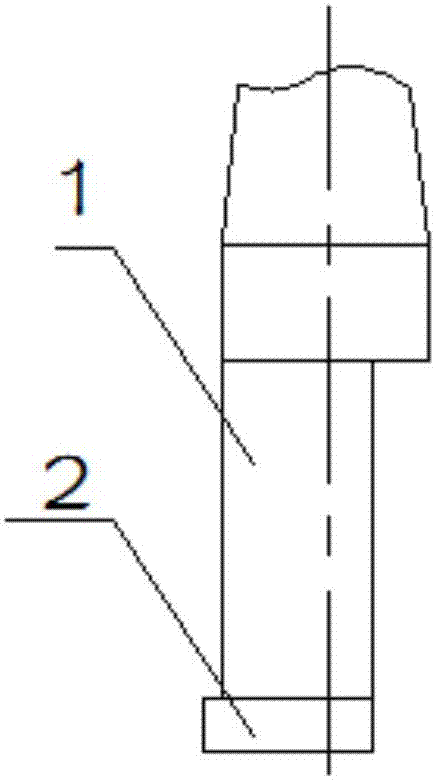
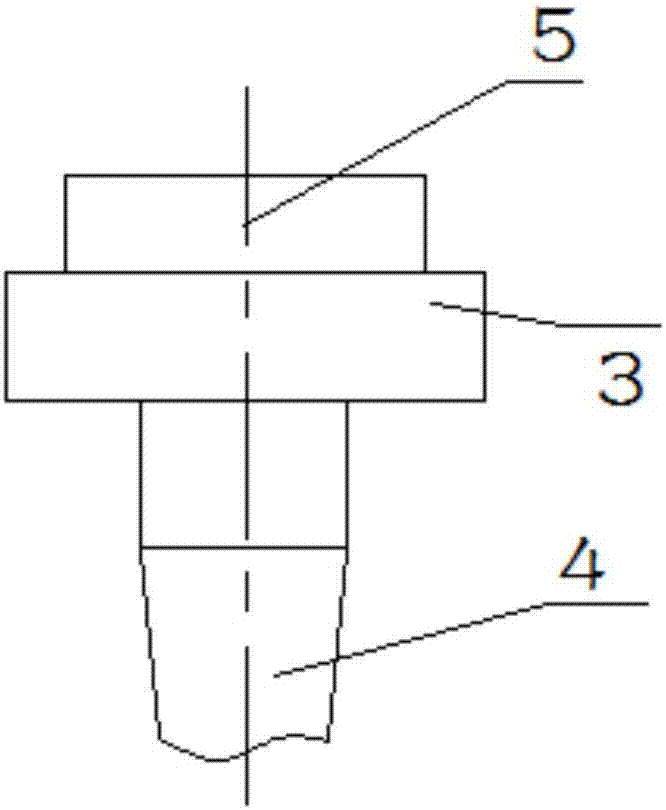
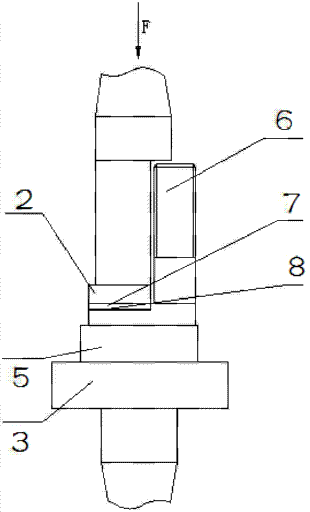
[0028] Such as figure 1 with figure 2 As shown, a contactor terminal assembly includes an upper electrode, a terminal and a lower electrode; the upper end of the terminal is connected to the upper electrode, and the lower end of the terminal is connected to the lower electrode; the upper electrode includes an upper electrode arm 1 and an upper electrode The electrical head 2, the upper electrical head 2 is arranged under the upper electrode arm 1; the lower electrode includes a lower electrode head 3, a lower electrode arm 4 and a resistance heat source 5. The upper end of the lower electrode head 3 is connected to the resistance heat source 5, and the lower end Connect the lower electrode arm 4; the upper electrode head 2 of the upper electrode is connected to the terminal through the contact 7 and the solder 8; the lower electrode tip 3 o...


PUM

PropertyMeasurementUnit
thicknessaaaaaaaaaa

Abstract

The invention provides a contactor binding post assembly which comprises an upper electrode, a binding post and a lower electrode. The upper end of the binding post is connected with the upper electrode, and the lower end of the binding post is connected with the lower electrode; the upper electrode comprises an upper-level electrode arm and an upper-level electrode head, and the upper-level electrode head is arranged on the lower portion of the upper-level electrode arm; the lower electrode comprises a lower-level electrode head, a lower-level electrode arm and a resistance heat source, the upper end of the lower-level electrode head is connected with the resistance heat source, and the lower end of the lower-level electrode head is connected with the lower-level electrode arm; and the upper-level electrode head of the upper electrode is connected with the binding post through a contact point and a brazing material, and the lower-level electrode head of the lower electrode is connected with the binding post through the resistance heat source. According to the contactor binding post assembly, spreading of the brazing material is improved, the brazed rate of a brazing seam of the contact point and the binding post is increased, and the impact of brazing flux residues on a product is completely eradicated, so that the use property and reliability of the contactor product are improved, and high-end development of the product is promoted.

Description

Technical field [0001] The invention relates to a contactor terminal assembly and a brazing connection method, and belongs to the technical field of brazing connection. Background technique [0002] At present, in the production of contactors, the contacts and the terminals are connected by brazing to achieve the function of transmitting current. Therefore, the quality of the brazing seam at the connection between the contacts and the terminals will directly affect the performance and reliability of the product Sex. [0003] In the production of general contactor products, the terminal material is copper, which can form a good brazing joint with the contact. However, in the production of special-purpose contactor products, the terminal is required to withstand a large torque, so the copper material The terminal can not meet the requirements. Therefore, the terminal material can only use copper alloys, such as brass, beryllium bronze, etc. Because copper alloys contain many trace a...

Claims


Application Information

Patent Timeline
Patent Type & Authority Applications(China)
IPC IPC(8): B23K11/00H01R4/02H01R43/02
CPCB23K11/00H01R4/029H01R43/0214
Inventor 龙爱帮赵先烈万晓华
Owner GUIZHOU TIANYI ELECTRICAL
Why Eureka
Try Eureka