Belt shaping conveyor

A technology for conveyors and belts, which is applied in the field of belt shaping conveyors, can solve the problems of high labor intensity, low production efficiency, belt knotting, etc., and achieve the effect of automatically adjusting the tension of the belt

Pending Publication Date: 2017-12-22
东莞方皓汽车配件有限公司
View PDF0 Cites 1 Cited by
  • Summary
  • Abstract
  • Description
  • Claims
  • Application Information

AI Technical Summary

Problems solved by technology

[0002] The belts of the prior art are produced on an assembly line, and the belts need to be colored after they are produced. The belts of the prior art are directly piled up after they are produced, and then manually processed before being colored. It is easy to cause belt knots caused by joints and chaotic belts, so that when the belt enters the coloring process, there will be a jam at the knot, and in order to ensure that the belt is evenly colored, it must be ensured that the belt is smooth when entering the coloring process. It is straight without knots, so two people are usually required to monitor whether the belt is knotted when it enters the coloring process. Once a knot is knotted, it needs to be manually stopped immediately, resulting in low production efficiency, high labor intensity, and high production costs.

Method used


Image

  • Belt shaping conveyor
  • Belt shaping conveyor
  • Belt shaping conveyor

Examples


Embodiment Construction

[0027] The present invention will be further described below in conjunction with accompanying drawing:

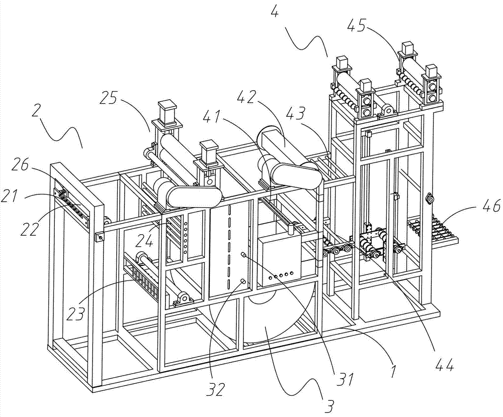
[0028] Such as Figure 1 to Figure 4 A kind of belt shaping conveyer shown, comprises frame 1, is arranged on the collection box 3 in the middle part of frame 1, is arranged on the first shaping conveying part 2 on the left side of collection box 3 and is arranged on collection box 3 The second shaping conveying part 4 on the right side;

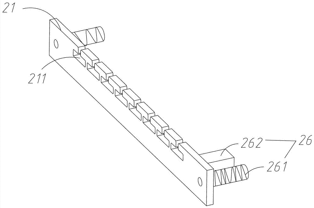
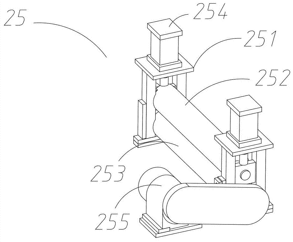
[0029] The first shaping and conveying part 2 includes a feed plate 21, a plurality of first rollers 22, a fence 23, a first guide roller group 24 and a belt traction device 25, and the feed plate 21 is arranged at the upper left end of the frame 1 , the fence 23 is arranged on the lower right side of the feed plate 21, the first idler roller group 24 is vertically arranged on the upper right side of the fence 23, the belt traction device 25 is arranged on the upper right side of the fence 23, and the feeding The material plate 21 is al...


PUM


Abstract

The invention provides a belt shaping conveyor. The belt shaping conveyor comprises a rack, a material collecting box, a first shaping conveying part and a second shaping conveying part; the first shaping conveying part comprises a feeding plate, a plurality of first carrier rollers, a fence, a first guiding roller set and a belt traction device; a knotting induction device is further arranged on the feeding plate; a first induction device and a second induction device capable of detecting the belt capacity are arranged in the material collecting box; the second shaping conveying part comprises a material guiding plate, a triangular carrier roller, a second guiding roller set, a third guiding roller set, a belt tensioning device and a fourth guiding roller set; the belt tensioning device comprises belt pressing flattening devices, a second carrier roller and a balance weight guiding roller set; the belt pressing flattening devices are arranged above the rack; the second carrier roller is arranged between the belt pressing flattening devices; and the balance weight guiding roller set is arranged below the second carrier roller in an up-down lifting manner. The belt shaping conveyor has the beneficial effects that it can be guaranteed that the belt is not knotted when entering the coloring procedure, long time monitoring by a worker is not needed, and the belt can be automatically corrected and flattened.

Description

technical field [0001] The invention relates to the field of belt production equipment, in particular to a belt shaping conveyor. Background technique [0002] The belts of the prior art are produced on an assembly line, and the belts need to be colored after they are produced. The belts of the prior art are directly piled up after they are produced, and then manually processed before being colored. It is easy to cause the belt to be knotted due to joints and chaotic belts, so when the belt enters the coloring process, there will be a jam at the knot, and in order to ensure that the belt is evenly colored, it must be ensured that the belt is smooth when entering the coloring process. It is not knotted, so two people are usually required to monitor whether the belt is knotted when it enters the coloring process. Once a knot is knotted, it needs to be manually stopped immediately, resulting in low production efficiency, high labor intensity, and high production costs. Conten...

Claims


Application Information

Patent Timeline
IPC IPC(8): B65H26/02B65H23/26B65H20/30B65H23/16B65H23/188
CPCB65H20/30B65H23/16B65H23/188B65H23/26B65H26/02B65H2404/15B65H2515/314B65H2515/34B65H2553/80B65H2601/11B65H2701/19B65H2515/10B65H2220/01B65H2220/03B65H2220/02
Inventor 李方伦王万发兰洁黄国交
Owner 东莞方皓汽车配件有限公司
Why Eureka
Try Eureka