Latching device and gas transmission station pressure regulation safety cut-off valve

A locking device and valve stem technology, applied in safety valves, valve devices, valve operation/release devices, etc., can solve problems such as hidden safety hazards, inaccurate detection pressure, false shutdown of SSV valves, etc., and achieve anti-vibration capabilities. Strong, realize real-time feedback, close the effect of good performance

Pending Publication Date: 2017-12-22
CHINA PETROLEUM & CHEM CORP +1
View PDF7 Cites 11 Cited by
  • Summary
  • Abstract
  • Description
  • Claims
  • Application Information

AI Technical Summary

Problems solved by technology

[0004] 1. Because the solenoid valve in the existing interlocking drive device is prone to internal leakage after more than ten switching tests, even under the condition of dirty air, the internal leakage will occur even after switching once, causing the SSV valve to be closed by mistake. When the solenoid valve is found In the case of internal leakage, only the valve at the root of the gas path can be closed, but the pressure regulating branch loses the ESD cut-off function, and there are certain safety hazards. It cannot be cut off immediately in case of sudden leakage or fire in the gas transmission station. lead to secondary disasters
[0005] 2. The existing interlocking drive device senses the downstream pressure by a spring sensor, and the interlocking drive is cut off when the pressure is over or under pressure. Due to the long-term use of the spring, it is easy to deform and age, resulting in inaccurate detection of pressure, which is lacking in the long run. reliability

Method used


Image

  • Latching device and gas transmission station pressure regulation safety cut-off valve
  • Latching device and gas transmission station pressure regulation safety cut-off valve
  • Latching device and gas transmission station pressure regulation safety cut-off valve

Examples


Embodiment Construction

[0038] The principles and features of the present invention are described below in conjunction with the accompanying drawings, and the examples given are only used to explain the present invention, and are not intended to limit the scope of the present invention.

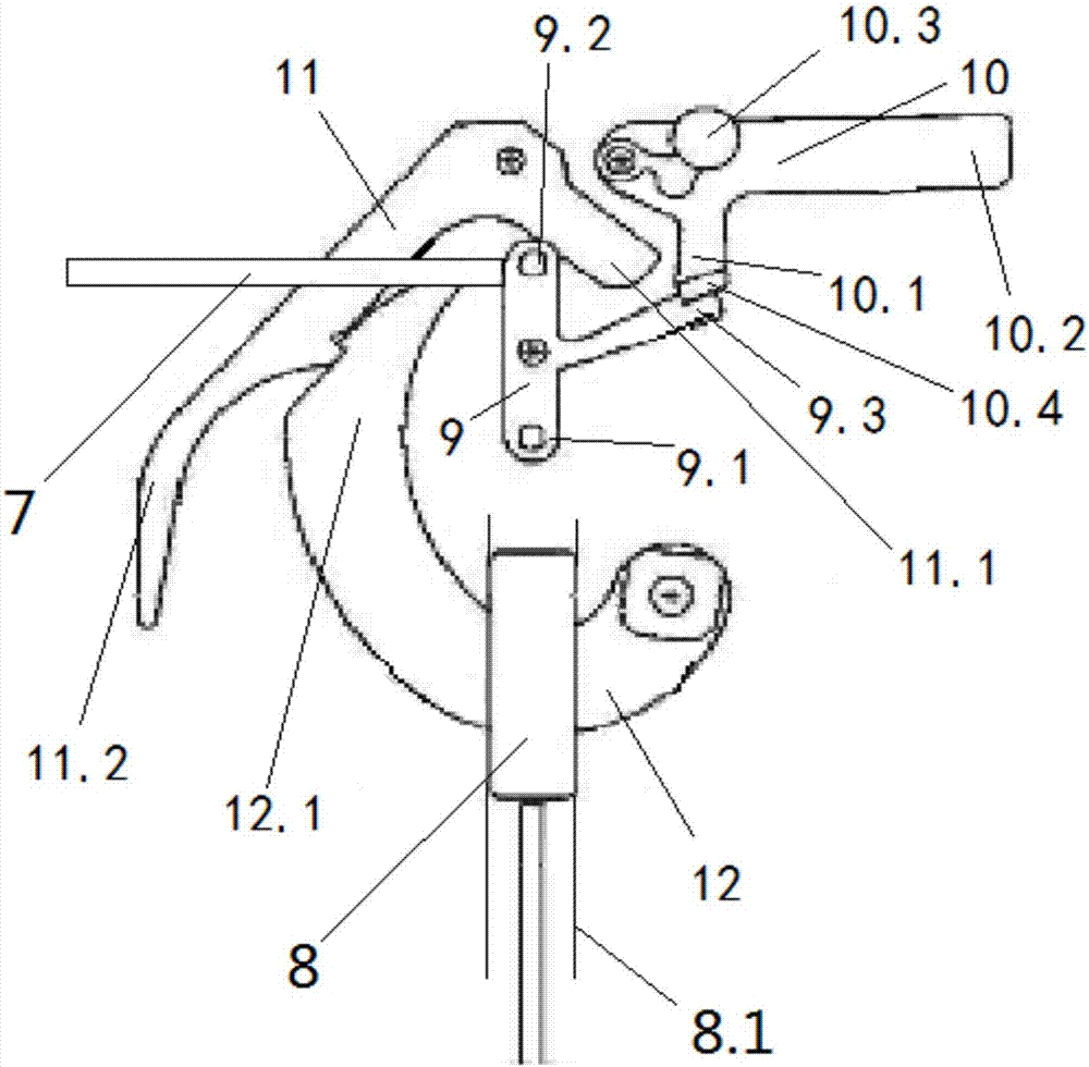
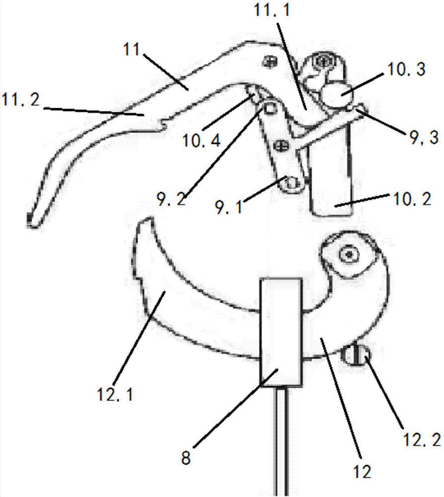
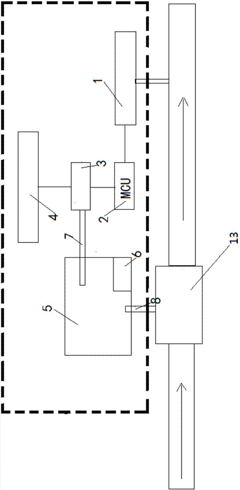
[0039] Such as figure 1 As shown, a locking device includes a mechanical case 5, a valve stem 8, a release lever 9, a first-stage trigger 10, a second-stage trigger 11, and a cam 12; the mechanical case 5 is a hollow cuboid structure;

[0040] The release lever 9 is rotationally connected with the inner wall of the mechanical box 5 through the release lever shaft arranged at the middle part of the release lever 9; the release lever 9 includes at least two ends: the release lever upper end 9.2 and the release lever side end extending to the upper right of the release lever axis 9.3;

[0041] The first stage trigger 10 is arranged on the upper right side of the release lever 9; the first stage trigger 10 is rotatably...


PUM


Abstract

The invention relates to a latching device and a gas transmission station pressure regulation safety cut-off valve. The gas transmission station pressure regulation safety cut-off valve comprises the latching device, a pressure sensor, an MCU, an electromagnet and a gate valve body, wherein the pressure sensor is connected with the MCU; the MCU is electrically connected with the electromagnet; a control end of the electromagnet is connected with an ejector rod; the gate valve body is connected with a valve rod; and when pressure measured by the pressure sensor exceeds a threshold valve, the MCU sends out an electric signal, the electromagnet is energized, the electromagnet drives the ejector rod, the valve rod falls off, and the gate valve body is cut off. According to the latching device and the gas transmission station pressure regulation safety cut-off valve, when abnormities like overpressure and pressure loss of downstream pressure are detected, the safety cut-off valve can be quickly cut off; when emergency switching-off is executed, driving is carried out through the electromagnet, and the general service life reaches millions of times; besides, the electromagnet is energized, and the situation that an interlock driving device performs mistaken action is avoided; and the shock resistance is high, closing performance is good, and real-time feedback of the valve state can be achieved.

Description

technical field [0001] The invention relates to petroleum and natural gas equipment, in particular to a locking device and a pressure regulating safety cut-off valve for a gas transmission station. Background technique [0002] At present, natural gas transmission stations mainly use pressure regulating skids to adjust the gas transmission pressure and flow rate to ensure safe production downstream. The pressure regulating skid adopts SSV (emergency shut-off valve), PCV (monitoring pressure regulating valve) and PV (working pressure regulating valve) in series to form a pressure control system. Under normal circumstances, the safety cut-off valve and the monitoring pressure regulating valve are in the fully open position, and the downstream pressure is controlled by the working regulating valve; when the working regulating valve fails and the downstream pressure cannot be controlled, the monitoring pressure regulating valve starts to work to maintain the downstream pressure ...

Claims


Application Information

Patent Timeline
Patent Type & Authority Applications(China)
IPC IPC(8): F16K17/02F16K31/06
CPCF16K17/02F16K31/06
Inventor 鞠海荣朱玉杰黄程周海亮范婷婷王喜卓陈家宁宋永林
Owner CHINA PETROLEUM & CHEM CORP
Why Eureka
Try Eureka