Unloading device, incinerator and sludge treatment method

A technology of unloading device and incinerator, which is applied in the direction of combustion method, incinerator, combustion type, etc., and can solve the problems of insufficient sludge combustion and low efficiency of incinerator treatment

Active Publication Date: 2017-12-22
YANCHENG HAIDENENG WATER TREATMENT ENVIRONMENTAL ENG
View PDF4 Cites 3 Cited by
  • Summary
  • Abstract
  • Description
  • Claims
  • Application Information

AI Technical Summary

Problems solved by technology

The current vertical incinerator unloading device has the defects of i

Method used


Image

  • Unloading device, incinerator and sludge treatment method
  • Unloading device, incinerator and sludge treatment method
  • Unloading device, incinerator and sludge treatment method

Examples


Embodiment 1

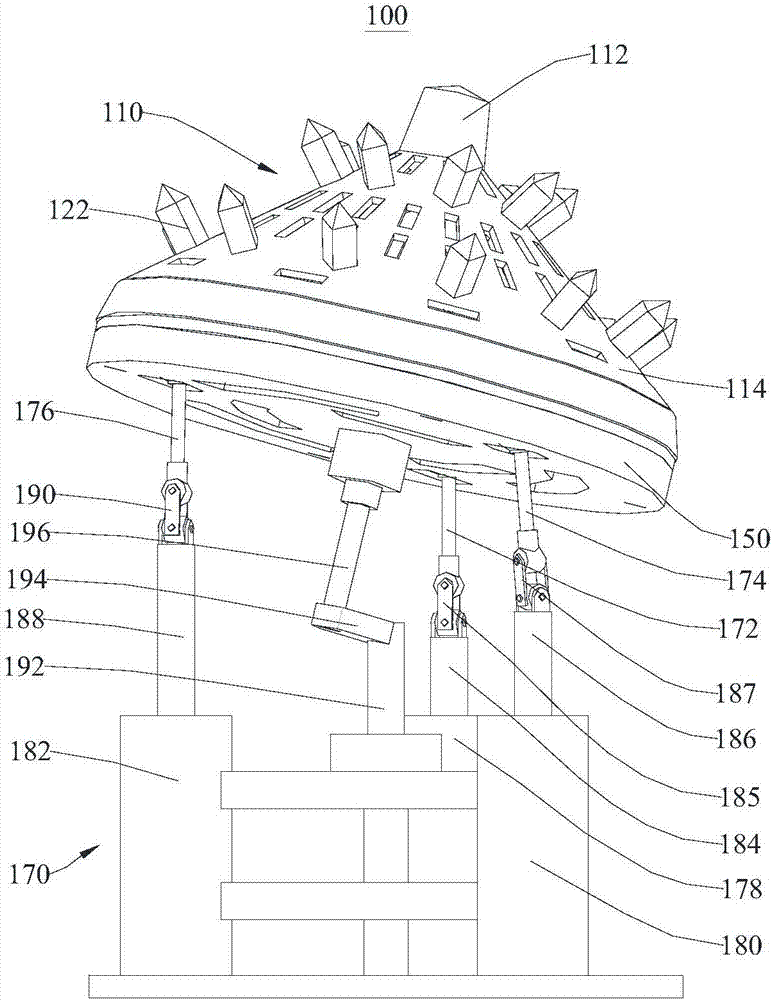
[0038] Please refer to figure 1 , figure 1Shown is a schematic structural view of the unloading device 100 . This embodiment provides a discharge device 100, which is mainly used for incinerating sludge with a sludge incinerator, and supporting and discharging the sludge.

[0039] In this embodiment, the unloading device 100 includes a unloading tower 110 , a support plate 150 and a support assembly 170 connected in sequence. The support assembly 170 provides support for the unloading tower 110 and the support plate 150, so that the unloading tower 110 can provide stable support for the materials in the combustion process (mainly referring to sludge in this embodiment), and can also discharge the burned materials. Perform stable discharge. The support assembly 170 can also swing the unloading tower 110 through the support plate 150, so as to tumbling and loosen the burning materials, so that the materials can be burned more fully, and the combustion treatment efficiency of ...

Embodiment 2

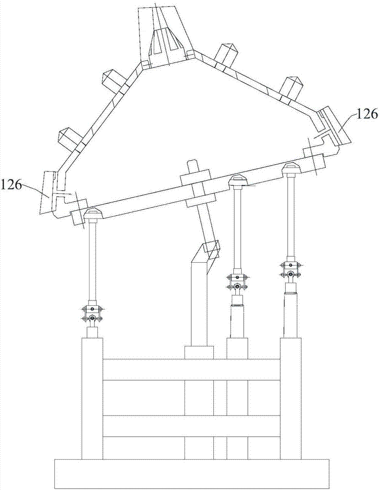
[0055] Please refer to Figure 5 , Figure 5 Shown is a schematic structural view of the incinerator 300 . This embodiment provides an incinerator 300 , including a furnace body 310 and a discharge device 100 , and the discharge device 100 is located at the bottom of the furnace body 310 . The inner furnace wall of the furnace body 310 is provided with a second jaw plate 312 , and the second jaw plate 312 is spaced apart from the first jaw plate 126 . When the unloading tower 110 is in a bumpy state, the slag after the incineration of the material (mainly referring to sludge in this embodiment) passes through the gap between the first jaw plate 126 and the second jaw plate 312 and the unloading tower 110 itself has opening for unloading. Both the first jaw plate 126 and the second jaw plate 312 are made of wear-resistant materials, and the surfaces of the two jaw plates are concave-convex. During mutual movement, the slag can be crushed to make the discharge even.

[0056]...


PUM


Abstract

The invention provides an unloading device, an incinerator and a sludge treatment method and relates to the technical field of environment protection. The unloading device comprises a supporting assembly and a supporting plate, which are connected with each other. The supporting assembly comprises a first supporting rod and a second supporting rod. The first supporting rod and the second supporting rod are in rotary connection with the supporting plate. The first supporting rod can be retracted in the length direction of the first supporting rod so that the supporting plate can rotate in the vertical direction. The second supporting rod can be retracted in the length direction of the second supporting rod so that the supporting plate can rotate in the vertical direction. A first through hole is formed in the supporting plate. The two supporting rods are used for commonly supporting the supporting plate so that the bearing stability of the unloading device is improved. The two supporting rods are in retractable matching, so that the supporting plate can rotate in the vertical direction to form jolted swinging; and meanwhile, materials on the supporting plate are turned and loosened by utilizing the swinging, so that the materials are in sufficient contact with the air and the incineration efficiency of the materials is improved. The invention further provides the incinerator and the sludge treatment method.

Description

technical field [0001] The invention relates to the technical field of environmental protection, in particular to a discharge device, an incinerator and a sludge treatment method. Background technique [0002] At present, in our country, a large amount of sludge is produced in water resource management, urban sewage treatment and production process of some enterprises. These sludges contain a large number of bacteria, insect eggs, heavy metals and organic matter, etc., if not handled properly, it will cause new pollution. [0003] The main methods of sludge disposal are sludge landfill, sludge incineration and sludge recycling. From the perspective of disposal effect, the sludge treatment technology with incineration as the core is the most thorough sludge professional treatment method. It can carbonize all the organic matter in the sludge, burn dead pathogens, and realize complete inert treatment of sludge containing heavy metals or chemical pollutants, which can minimize ...

Claims


Application Information

Patent Timeline
IPC IPC(8): F23G7/00F23G5/44
CPCF23G5/44F23G7/00
Inventor 陈杰来许宁田晓峰温涛戴林政李帅莫全就颜东
Owner YANCHENG HAIDENENG WATER TREATMENT ENVIRONMENTAL ENG
Why Eureka
Try Eureka