Preprocessing method for optical proximity correction technology

An optical proximity correction and preprocessing technology, which is applied in the direction of electrical digital data processing, special data processing applications, instruments, etc., can solve problems such as variation and inability to remove graphic protrusions, so as to eliminate influence and improve accuracy and consistency Effect

Active Publication Date: 2017-12-22
SHANGHAI HUALI MICROELECTRONICS CORP
View PDF3 Cites 3 Cited by
  • Summary
  • Abstract
  • Description
  • Claims
  • Application Information

AI Technical Summary

Problems solved by technology

[0005] When there is a graphics bump (Jog) on ​​the 45-degree hypotenuse, the graphics bump cannot be removed by the traditional method, resulting in the possibility of abnormal correction in the OPC processing, or the post-OPC processing version Figure 1 Consistency variation

Method used


Image

  • Preprocessing method for optical proximity correction technology
  • Preprocessing method for optical proximity correction technology
  • Preprocessing method for optical proximity correction technology

Examples


Embodiment 1

[0047] Such as Figure 6 As shown, there is a graphic side bulge 2 on graphic 1, and graphic 1 has multiple graphic sides, one of which is at a 45° angle to the X axis, and graphic side bulge 2 is located on the 45° hypotenuse, and the graphic side is raised 2 is parallel to the X-axis, and the figure side protrusion 2 is less than 5nm, and the two figure sides adjacent to the figure side protrusion 2 are respectively the first figure side 3 and the second figure side 4 (the figure side protrusion 2 will be 45° The hypotenuse is divided into the first graphic edge 3 and the second graphic edge 4), the relative angle of the first graphic edge 3 and the graphic edge protrusion 2 at the inside of the graphic 1 is 225 °, the second graphic edge 4 and the graphic edge protrusion 2. The angle between the sex pairs inside the graph 1 is 135°, and all the graph edges and the graph edge protrusions 2 are located on the graph grid points based on the minimum precision grid;

[0048] Su...

Embodiment 2

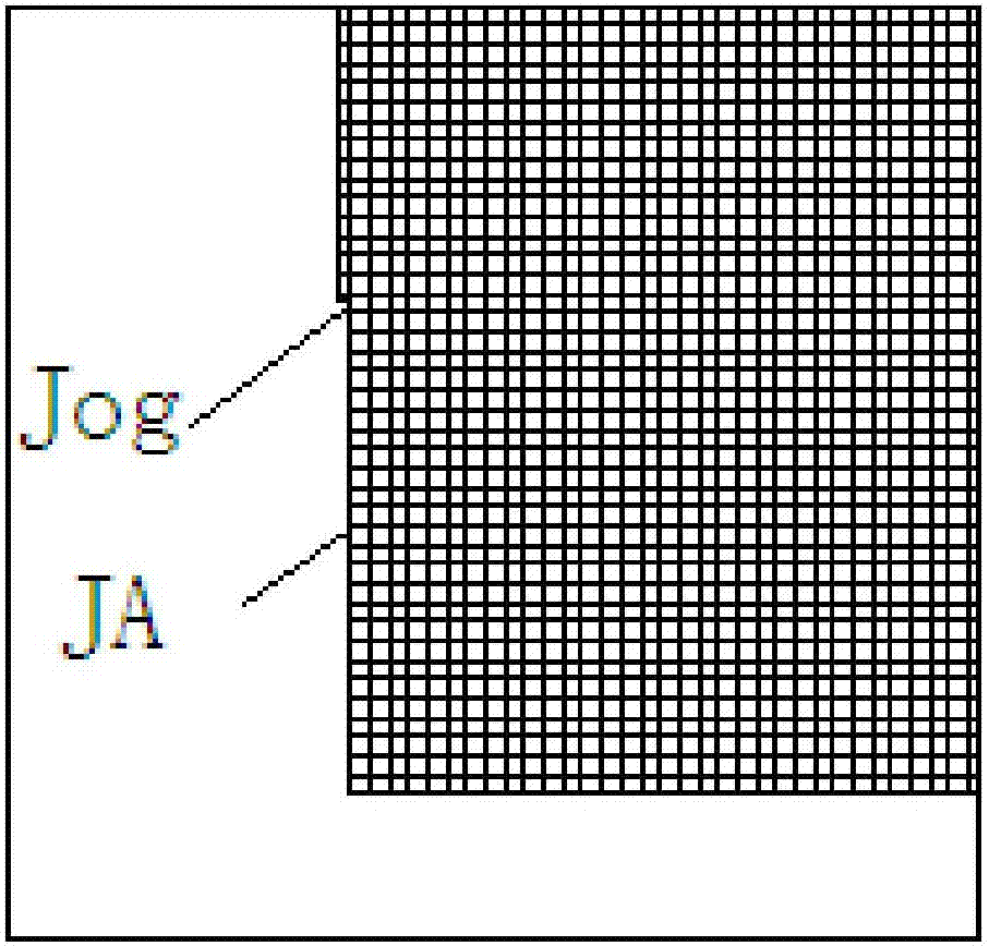
[0055] Such as Figure 15 As shown, there are two figure side protrusions 2 on figure 1 (both the short sides EJA1 and EJA2 are figure side protrusions 2), figure 1 has multiple figure sides, one of the figure sides is 45° to the X axis, and the figure side The bulge 2 is located on the 45° hypotenuse, the short side EJA1 is parallel to the X axis, and the short side EJA2 is perpendicular to the X axis. Before preprocessing, first determine the maximum length of the graphic side bulge 2, assuming that the graphic side bulge 2 The maximum length of the 45° hypotenuse is 2nm, and the maximum length of the 45° hypotenuse is 300nm. When there are two graphic sides protruding 2 on the 45° hypotenuse, then as Figure 15 shown.

[0056] Continue to refer to Figure 15 , first use the DRC tool to select all short sides EJA1 and EJA2 with a length less than 2nm in the graph PTA0, and these short sides form an angle of 0 degrees or 90 degrees with the coordinate axis;

[0057] Such a...


PUM


Abstract

The invention provides a preprocessing method for an optical proximity correction technology, and belongs to the technical field of integrated circuit design. The method comprises the following steps that: enabling a first graphic edge to extend to the outer side of a graph for a first preset distance so as to obtain a first rhombic graph; enabling a second graphic edge to extend to the outer side of the graph for a second preset distance to obtain a preprocessed coverage graph, and enabling the preprocessed coverage graph to extend a direction parallel with the second graph edge for a third preset distance to obtain a coverage graph which covers parts of first graph; carrying out logic ''NOT'' processing on the first graph and the coverage graph to obtain a second graph; carrying out logic "Or" processing on the graph and the second graph to obtain a first target graph with a chamfering notch; and carrying out triangular filling on the chamfering notch to obtain a second target graph. The preprocessing method has the beneficial effects that the accuracy and the consistency of an OPC (Optical Proximity Correction) processing result are improved.

Description

technical field [0001] The invention relates to the technical field of integrated circuit design, in particular to a preprocessing method for an optical proximity correction process. Background technique [0002] In the optical proximity correction (Optical Proximity Correction, OPC) process of integrated circuit publishing, the consistency of layout results has always been one of the difficulties. After the same or similar first target graphics are processed by large-area complete layout OPC, often appear There are many reasons for the difference in OPC results, and the bump (Jog) on ​​the edge of the graph is one of the important factors. [0003] In memory IC products, repetitive cells occupy most of the layout area. These repetitive units have the same design pattern, and the designer hopes to obtain the same pattern result on the silicon wafer through the mask. Affected by factors such as layout resolution, repetitive units may produce subtle differences during the pr...

Claims


Application Information

Patent Timeline
Patent Type & Authority Applications(China)
IPC IPC(8): G06F17/50
CPCG06F30/392
Inventor 何大权魏芳朱骏张旭升
Owner SHANGHAI HUALI MICROELECTRONICS CORP
Why Eureka
Try Eureka