Dustproof SDN switch

A switch and dust-proof technology, applied in the field of converters, can solve the problems of easy to absorb dust interface and internal components, large network fluctuation, easy to absorb dust and other problems, to achieve reliable guarantee, stable internal temperature, scientific and reasonable structure.

Active Publication Date: 2017-12-22
SHENZHEN MTN ELECTRONICS
12 Cites 0 Cited by

AI-Extracted Technical Summary

Problems solved by technology

[0004] The purpose of the present invention is to provide a dust-proof SDN switch to solve the problem that the high internal temperature of the switch proposed in the above background...

Abstract

The invention discloses a dustproof SDN switch comprising a lower cooling fin, an interface box dust cover and a flexible cable interface, wherein a machine body is arranged on an upper side face of the lower cooling fin, a power switch is arranged at a position close to the left side of the lower cooling fin at the middle position of the machine body, and a third cable interface box is arranged at a position close to the middle position of the machine body on the right side of the power switch, and an upper cooling fin is arranged on the upper side face; and it is beneficial to take away the heat dissipated by the switch at work, the upper and lower waves have different sizes, even if several switches are stacked together for use, the cooling performance is not affected, in addition, a segment of dustproof shell is added at the outside of the interface, thereby being able to not only prevent dust attracted due to long-term static, but also being able to prevent the damage to the cable joint caused by collision of the network cable at the interface, so that the internal temperature of the switch is relatively stable during operation, no network fluctuation is generated, and thus the switch can operate more stably.

Application Domain

Data switching networksSelection arrangements

Technology Topic

Heat sinkInternal temperature +2

Image

  • Dustproof SDN switch
  • Dustproof SDN switch
  • Dustproof SDN switch

Examples

  • Experimental program(1)

Example Embodiment

[0016] The technical solutions in the embodiments of the present invention will be clearly and completely described below in conjunction with the accompanying drawings in the embodiments of the present invention. Obviously, the described embodiments are only a part of the embodiments of the present invention, rather than all the embodiments. Based on the embodiments of the present invention, all other embodiments obtained by those of ordinary skill in the art without creative work shall fall within the protection scope of the present invention.
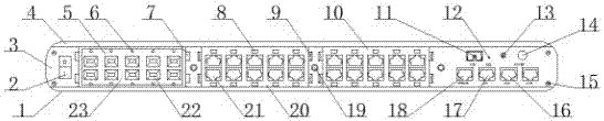
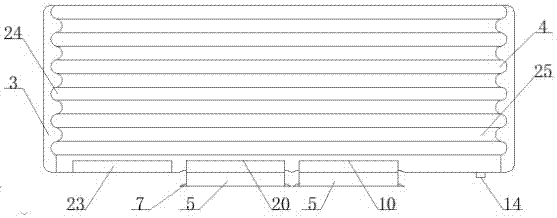
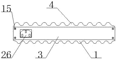
[0017] See Figure 1-4 , The present invention provides a technical solution: comprising a lower heat sink 1, an interface box dust-proof cover 5 and a flexible cable interface 22, the upper surface of the lower heat sink 1 is provided with an organism 3, and the middle position of the body 3 is close to the lower heat sink A power switch 2 is provided on the left side of 1, a third cable interface box 23 is provided on the right side of the power switch 2 near the middle of the body 3, an upper heat sink 4 is provided on the upper surface of 3, and a dust cover of the interface box 5 Installed in the middle position of the third cable interface box 23 near the right side of the power switch 2, the middle position of the interface box dust cover 5 is near the outside of the power switch 2 is provided with an indicator hole 6, a cable soft interface 22 Installed on the inner side of the indicator hole 6 near the middle position of the dust cover 5 of the interface box, the outer side of the cable soft interface 22 is close to the inner side of the indicator hole 6 is provided with a dust cover handle 7, and the third cable interface box 23 A second cable interface box 20 is provided on the right side. A dust cover handle groove 9 is provided on the right side of the second cable interface box 20 close to the dust cover handle 7, and the left side of the dust cover handle groove 9 is dustproof. A cable box fixing screw 19 is provided at the middle position on the right side of the cover handle 7, and a network cable interface 21 is provided at the inner side of the dust-proof cover handle groove 9 near the middle of the second cable interface box 20. A cable interface indicator light 8 is provided on the outside of 21, a first cable connection box 10 is provided on the right side of the second cable interface box 20 near the middle of the body 3, and the middle position of the body 3 is near the first connector. The upper side of the cable box 10 is provided with an optical fiber interface 11, the right middle position of the optical fiber interface 11 is provided with a reset hole 12, the right side of the reset hole 12 is provided with a power indicator 13, and the right middle of the power indicator 13 A cable switch 14 is arranged at the position, a housing fixing screw 15 is arranged on the outside of the body 3 close to the right side of the cable switch 14, and a spare network cable interface is arranged on the left side of the housing fixing screw 15 close to the lower side of the cable switch 14. 16. A network inlet port 17 is provided on the left side of the spare network cable interface 16 near the reset hole 12, and a branch switch interface 18 is provided on the left side of the network inlet port 17 near the right side of the first cable connection box 10 , The middle position of the upper heat sink 4 is close to the upper surface of the body 3 with a heat sink groove 25, the outside of the heat sink groove 25 is provided with a heat sink flange 24, the left side of the body 3 is close to the housing fixing screw 15 A power jack 26 is provided at the middle position on the right side of the, and the power jack 26 is electrically connected to an external power source.
[0018] In order to ensure the dustproof performance of the switch interface in use, in this embodiment, preferably, there are three interface box dustproof covers 5, and the three interface box dustproof covers 5 are all installed at the middle position of the body 3. .
[0019] In order to ensure that it is convenient to open the dustproof box when installing cables, in this embodiment, preferably, there are four dustproof cover handles 7 in total, and the four dustproof cover handles 7 are all installed on the dustproof cover 5 of the interface box. There are a total of four dust-proof cover handle grooves 9 provided on the outer side of the dust-proof cover, and the four dust-proof cover handle grooves 9 are all installed on the inner side of the dust-proof cover handle 7.
[0020] In order to ensure the reliability of the process of opening and closing the dust box, in this embodiment, preferably, the interface box dust cover 5 and the third cable interface box 23 are slidably connected by a slot, and the interface box dust cover 5 and the The two cable interface boxes 20 are slidably connected by a slot, and the interface box dust cover 5 and the first cable connection box 10 are slidably connected by a slot.
[0021] In order to ensure the overall stability of the machine body, in this embodiment, preferably, four housing fixing screws 15 are provided, and the four housing fixing screws 15 are all installed on the outside of the machine body 3.
[0022] The cable soft interface 22 in the present invention is made of retractable rubber, which can easily change the size of the interface, effectively prevent the entry of dust, and can freely pass through the cable joint.
[0023] The working principle and use process of the present invention: After the present invention is installed, the power switch 2 is connected to the external power supply, and then the optical fiber or network cable is inserted into the optical fiber interface 11 or the network inlet interface 17, and the spare network cable interface 16, and then Press the cable switch 14 to turn on the switch of the network cable, and then insert the network cables on the device into the network cables in the first connection cable box 10, the second cable interface box 20, and the third cable interface box 23, respectively. On the cable interface 21, open the dust cover 5 of the interface box through the dust cover handle 7 in front of the dust cover handle slot 9 on the body 3, and insert the cable into the network cable interface 21 through the cable soft interface 22. The cable interface indicator light 8 is on, indicating a successful installation.
[0024] Although the embodiments of the present invention have been shown and described, those of ordinary skill in the art can understand that various changes, modifications, and substitutions can be made to these embodiments without departing from the principle and spirit of the present invention. And variations, the scope of the present invention is defined by the appended claims and their equivalents.

PUM

no PUM

Description & Claims & Application Information

We can also present the details of the Description, Claims and Application information to help users get a comprehensive understanding of the technical details of the patent, such as background art, summary of invention, brief description of drawings, description of embodiments, and other original content. On the other hand, users can also determine the specific scope of protection of the technology through the list of claims; as well as understand the changes in the life cycle of the technology with the presentation of the patent timeline. Login to view more.

Similar technology patents

Classification and recommendation of technical efficacy words

  • safe to use
  • Scientific and reasonable structure

Stretchable nonwoven fabric and tape

ActiveUS20100035500A1high stretchabilitysafe to use
Owner:KURARAY CO LTD

Air fryer

PendingCN108552969Asafe to use
Owner:YUEDA ELECTRONICS TECH

Affixation of objects to garments

ActiveUS9345433B1safe to use
Owner:SENSARX
Why Eureka
Try Eureka