Preparation method of fluorescent polarizing film based on directional arrangement of quantum rods

A technology of directional alignment and fluorescence polarization, which is applied in polarizing components, chemical instruments and methods, and printing of special varieties of printed matter, can solve the problems of limited directional effect and large material loss, and achieves easy operation, simple experimental equipment, and extensive The effect of applicability

Active Publication Date: 2017-12-26
SOUTH UNIVERSITY OF SCIENCE AND TECHNOLOGY OF CHINA
View PDF12 Cites 14 Cited by
  • Summary
  • Abstract
  • Description
  • Claims
  • Application Information

AI Technical Summary

Problems solved by technology

At present, there are not many methods for aligning quantum rod materials, such as quantum rod film mate...

Method used


Image

  • Preparation method of fluorescent polarizing film based on directional arrangement of quantum rods
  • Preparation method of fluorescent polarizing film based on directional arrangement of quantum rods
  • Preparation method of fluorescent polarizing film based on directional arrangement of quantum rods

Examples


Embodiment 1

[0066] In this example, the aligned quantum rod thin film is prepared by the following method, which specifically includes the following steps:

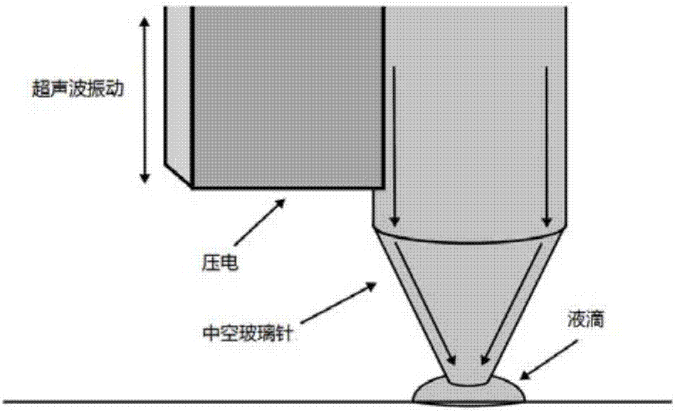
[0067] The quantum rod material CdSe / CdS is prepared into the quantum rod ink by solvent toluene, the concentration of the quantum rod ink is 20mg / mL; the quantum rod ink is injected into the solution plate, and the inkjet printing needle is immersed in the quantum rod ink in the solution plate, The needle will attract the solution into the needle, select the upper left corner of the ordinary glass substrate as the coordinate origin, move the needle to the bottom of the printer by moving the printer’s mechanical arm, lower the needle until it touches the surface of the printing substrate, import and print the preset graphics, follow the preset Set the graph to print ( image 3 It is an enlarged schematic diagram of the structure of the needle head part of the printer used in the present invention), when printing is carried out, such ...

Embodiment 2

[0073] In this example, the aligned quantum rod thin film is prepared by the following method, which specifically includes the following steps:

[0074] The red quantum rod material is prepared into quantum rod ink with a mixed solvent of toluene and o-dichlorobenzene, the concentration of quantum rod ink is 40mg / mL; the quantum rod ink is injected into the solution plate, and the inkjet printing needle is immersed in the solution plate. In the quantum rod ink, the needle will attract the solution into the needle, select the upper left corner of the ITO conductive glass substrate as the coordinate origin, move the needle to the bottom of the printer by moving the printer’s mechanical arm, lower the needle until it touches the surface of the printing substrate, and start printing Preset graphics, print according to the preset graphics ( image 3 It is an enlarged schematic diagram of the structure of the needle head part of the printer used in the present invention), when print...

Embodiment 3

[0077] In this example, the aligned quantum rod thin film is prepared by the following method, which specifically includes the following steps:

[0078] The blue quantum rod material is prepared into quantum rod ink with toluene, and the concentration of quantum rod ink is 10mg / mL; the quantum rod ink is injected into the solution plate, and the inkjet printing needle is immersed in the quantum rod ink in the solution plate, and the needle will The solution is sucked into the needle, select the upper left corner of the PET substrate as the coordinate origin, move the needle to the bottom of the printer by moving the printer arm, lower the needle until the needle touches the surface of the printing substrate, import and print the preset graphics, and proceed according to the preset graphics Print( image 3 It is an enlarged schematic diagram of the structure of the needle head part of the printer used in the present invention), when printing is carried out, such as Figure 4 A...


PUM


Abstract

The invention provides a preparation method of a fluorescent polarizing film based on directional arrangement of quantum rods. In the method, an ink-jet printing technology is used to print quantum-rod ink with proper viscosity and surface tension on a substrate according to a preset pattern and arrange the quantum rods in a certain direction to obtain the fluorescent polarizing film. The diameter and the line spacing of fluorescent lines obtained by the method provided by the invention can be controlled and adjusted by parameter conditions such as needle aperture, printing speed, preset pattern and the like. The prepared transparent fluorescent film with directionally arranged quantum rods has a high degree of polarization, can be prepared on a flexible substrate in a normal temperature environment, and has wide applicability.

Description

technical field [0001] The invention belongs to the technical field of photoelectric material preparation, and relates to a method for aligning quantum rods, in particular to a method for preparing a fluorescence polarizing film based on quantum rod alignment. Background technique [0002] At present, there are many studies on the polarization properties of quantum rods, but most of them are for the analysis of single-particle quantum rods, and there are few in-depth studies on the analysis of the overall polarization under the joint action of a large number of quantum rods, because the polarization effect of quantum rods is along the Axial direction of rod material. However, in the case of a large number of free distribution of quantum rods, it cannot show good polarization performance as a whole. Only when the quantum rods are arranged in an orderly manner can polarized light be effectively emitted. [0003] At present, ordered one-dimensional nanowires can be fabricated ...

Claims


Application Information

Patent Timeline
IPC IPC(8): C09D11/03C09D11/30
CPCC09D11/03C09D11/30C09K11/562C09K11/883B41M3/003B41J2/005B82Y20/00B82Y40/00G02B5/30B41J2/155B41M1/30B82Y30/00C09D11/38B41J2/17
Inventor 孙小卫王恺刘皓宸周子明张哲郝俊杰温佐良
Owner SOUTH UNIVERSITY OF SCIENCE AND TECHNOLOGY OF CHINA
Why Eureka
Try Eureka