
Water pump control system used for low water period of power plant construction

A control system and water pump technology, applied in the direction of pump control, pump, pump device, etc., can solve problems such as burning, and achieve the effect of reducing workload, avoiding burning and reliable water source

Inactive Publication Date: 2017-12-26
STATE GRID CORP OF CHINA +2
View PDF5 Cites 0 Cited by
  • Summary
  • Abstract
  • Description
  • Claims
  • Application Information

AI Technical Summary

Problems solved by technology

During the dry season, as long as the water tank is not filled to the standard water level, the power contactor of the water pump will always be closed, resulting in frequent burnouts. As a result, the water supply in the living area of ​​the permanent camp can only be used in a limited amount, which can only meet the needs of the canteen and a small amount of domestic water.

Method used


Image

  • Water pump control system used for low water period of power plant construction

Examples


Embodiment Construction

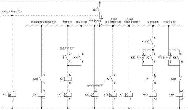
[0016] see figure 1 , the names of the components are as follows: flow switch K2, main switch CB, primary pump contactor KM1, backup pump contactor KM2, flow switch K2, time relay KT0 for delayed opening and delayed closing, obtained from the standby pump contactor The intermediate relay K1 for closed contacts, the absolute closing time relay KT4, the time relay KT3 for delaying the start of the standby pump, the time relay KT2 for the delay before the standby pump obtains the flow, and the time relay KT1 for the delay before the main pump obtains the flow.

[0017] see figure 1 , used for the water pump control system in the dry season of power station construction, including the main pump and the backup pump at the two water sources. The main pump and the backup pump are connected to the water tank in the living area through pipelines. The flow switch K2 controls the start and stop of the water pump according to the flow rate; the control circuit includes the main switch CB...


PUM


Abstract

The invention relates to the field of water supply control, in particular to a water pump control system used for the low water period of power plant construction. The water pump control system comprises a main pump and a standby pump which are located at two water sources. The main pump and the standby pump are connected with a water tank of a living area through pipelines. A flow switch K2 is mounted at a main water inlet pipe in front of the water tank and controls starting and stopping of the water pumps according to the flow. A control circuit comprises a main switch CB, a main pump contactor KM1 and a standby pump contactor KM2, wherein the main pump contactor KM1 and the standby pump contactor KM2 are in parallel connection and are both connected with the flow switch K2. A normally-closed contact of the standby pump contactor KM2 is in series connection with the main pump contactor KM1. The two water pumps are arranged to operate respectively. When the flow of the main pump is reduced, the main pump stops operating, and meanwhile the standby pump is automatically started. When the flow of the standby pump is reduced, the main pump and the standby pump stop operation simultaneously. After water level of a water well recovers in a certain time, control circulation can be repeated till the water tank is injected to the standard water level, and overburning of the water pumps is avoided.

Description

technical field [0001] The invention relates to the field of water supply control, namely a water pump control system used in the dry season of power station construction. Background technique [0002] In the existing technology, the construction of pumped storage power stations has been booming in recent years. Since the water resources of pumped storage power stations can be recycled, the natural runoff only needs to meet the needs of reservoir evaporation and cooling of some equipment. Therefore, pumped storage power stations It can be built in areas where water is not abundant. After the construction of the power station, the domestic water can be taken from the built reservoir, but during the construction period of the power station, the domestic water can only be obtained from underground water resources through wells. In the dry season between spring and summer, there is a risk of the water intake pump being burned due to the drop in water level. [0003] When the o...

Claims


Application Information

Patent Timeline
Patent Type & Authority Applications(China)
IPC IPC(8): F04B49/06F04B23/04
CPCF04B23/04F04B49/06
Inventor 訾士才田鹏马龙彪王辉伟马信武李宁李军贺侯金良王添何雪飞庄延霞魏刚赵璐
Owner STATE GRID CORP OF CHINA
Learn More