
Electrically-controlled sealing-type reducing valve for vehicle fuel gas

A sealing type, pressure reducing valve technology, applied in the field of sealing type pressure reducing valve, can solve the problems of poor sealing and prolong the service life, and achieve the effect of improving high temperature wear resistance and prolonging the service life.

Inactive Publication Date: 2017-12-26
SICHUAN SENJIE GAS EQUIP CO LTD
View PDF5 Cites 2 Cited by
  • Summary
  • Abstract
  • Description
  • Claims
  • Application Information

AI Technical Summary

Problems solved by technology

[0005] The invention provides a sealed pressure reducing valve for automobile gas electric control. Through the installation of the power head, the valve core is driven to rotate 90°, and the flow path on the valve core also changes accordingly, thereby realizing the opening and closing of the valve. Closing function, by setting a ceramic coating on the valve core, the high temperature wear resistance of the valve sealing surface is improved, the service life is extended, and the technical problem of poor sealing is solved

Method used


Image

  • Electrically-controlled sealing-type reducing valve for vehicle fuel gas

Examples


Embodiment 1

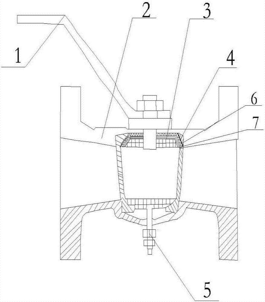
[0021] Such as figure 1 As shown, a sealed pressure reducing valve for automobile gas electric control, including a power head 1, a valve body 2, a valve core 3, an annular valve seat 4, and an adjusting screw 7, and the power head 1 is installed on the annular valve seat 4, there are two annular valve seats 4, and they are arranged oppositely. The power head 1 is installed on one of the annular valve seats 4, and a valve core 3 is installed between the two annular valve seats 4. The middle of the body 2 forms a flow channel for the flow of the liquid medium. The contact surface of the valve body 2 and the two annular valve seats 4 and the slow direction of the flange end respectively have an inclination angle of 5-10°. The two annular valve seats 4 An adjustment screw 5 is provided at the end far away from the power head 1;

[0022] A sealing ring 6 is provided between the valve core 3 and the annular valve seat 4 , and a hard cermet coating 7 is coated on the outer surface ...


PUM


Abstract

The invention discloses an electrically-controlled sealing-type reducing valve for vehicle fuel gas. The electrically-controlled sealing-type reducing valve comprises a power head, a valve body, a valve core, annular valve bases and adjusting bolts, wherein the power head is installed on one annular valve base, two annular valve bases are oppositely arranged, the power head is installed on one of the two annular valve bases, the valve core is installed between the two annular valve bases, a flow way for a liquid medium to flow past is formed in the middle of the valve body, the inclination angles of the contact surfaces of the valve body and the two annular valve bases in the direction of a flange end are 5-10 degrees respectively, the adjusting bolts are arranged at the ends, away from the power head, of the two annular valve bases, sealing rings are arranged between the valve core and the annular valve bases, and the outer surface of the valve core is coated with a layer of hard metal ceramic coating. According to the technical scheme, the hard metal coating is arranged on the valve core and is prepared through a plasma surface spraying treatment technology, the high-temperature wear resistance of a sealing surface of the valve can be effectively improved, and the service life of the valve is prolonged.

Description

technical field [0001] The invention relates to the technical field of valve accessories, in particular to a sealed pressure reducing valve used for electric control of automobile gas. Background technique [0002] Pressure reducer, because the pressure in the gas cylinder is high, but the pressure required for gas welding and gas cutting and the point of use is relatively small, so a pressure reducer is needed to reduce the high-pressure gas stored in the gas cylinder to low-pressure gas , and should ensure that the required working pressure remains stable throughout. In short, the pressure reducer is a regulating device that reduces high-pressure gas to low-pressure gas and keeps the pressure and flow of the output gas stable. However, the existing valves cannot be adaptively adjusted according to the adjustment of the fluid flow rate, and cannot meet the needs. [0003] The surface of the valve seat of the existing valve is severely worn, especially when the liquid medi...

Claims


Application Information

Patent Timeline
IPC IPC(8): F16K5/02F16K5/08F16K27/06
CPCF16K5/0257F16K5/08F16K27/062
Inventor 何松龙
Owner SICHUAN SENJIE GAS EQUIP CO LTD
Learn More