Hot air heat exchanger of biomass combustion equipment

A heat exchanger and biomass particle technology, which is applied in the field of the feed device of biomass combustion equipment, can solve the problems of low heat exchange efficiency, and achieve the effects of long heat exchange time, clean hot air and reduced heat loss.

Inactive Publication Date: 2017-12-26
广西节得乐生物质能源科技有限公司
View PDF0 Cites 1 Cited by
  • Summary
  • Abstract
  • Description
  • Claims
  • Application Information

AI Technical Summary

Problems solved by technology

[0003] The purpose of the present invention is to overcome the deficiencies of the prior art and provide a hot air heat exchanger with simple structure, low cost, energy saving and environmental protection, and high heat exchange efficiency. Good, solve the problem of low heat exchange efficiency, safe and reliable, reduce heat loss

Method used


Image

  • Hot air heat exchanger of biomass combustion equipment
  • Hot air heat exchanger of biomass combustion equipment
  • Hot air heat exchanger of biomass combustion equipment

Examples


Embodiment Construction

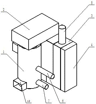
[0023] Such as figure 1 Shown, a kind of biomass particle hot air heat exchanger is characterized in that: comprise combustion chamber 1, flue gas box 3, heat exchange pipeline 13 and air reversing box 4;

[0024] The combustion chamber 1 is provided with a feed port 6, and the smoke box is provided with a smoke exhaust port 5;

[0025] Such as figure 2 As shown, the hot air chamber 11 surrounds the outer wall of the combustion chamber 1, and the hot air chamber 11 is provided with a hot air inlet 8 and a hot air outlet 9;

[0026] Such as Figure 1~Figure 2 As shown, the combustion chamber 1 is connected to the smoke box 3 through the smoke channel 2 , the combustion chamber 1 is connected to the inlet of the smoke channel 2 , and the outlet of the smoke channel 2 is connected to the smoke inlet of the smoke box 3 .

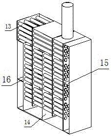
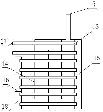
[0027] Such as Figure 3~Figure 4 As shown, the combustion chamber 1 is connected to the flue gas box 3, the flue gas generated by the combustion chamber 1...


PUM


Abstract

The invention discloses a biomass particle hot air heat exchanger. The biomass particle hot air heat exchanger comprises a combustion chamber, a smoke box, a heat exchange pipeline and air reversing boxes. A feeding port and a smoke discharging port are formed in the combustion chamber. A hot air chamber surrounds the outer wall of the combustion chamber. The hot air chamber is provided with a hot air inlet and a hot air outlet. The combustion chamber is connected with the smoke box. Smoke generated through the combustion chamber flows through the smoke box and is discharged through a smoke discharging port of the smoke box. The heat exchange pipeline penetrates a smoke heat exchange pipeline from left to right to connect the air reversing boxes arranged on the left side and the right side of the heat exchange pipeline. A hot air channel is formed by the heat exchange pipeline and cavities of the air reversing boxes, air enters from an air inlet, and air enters the hot air inlet of the hot air chamber after flowing and being subjected to heat exchange in the hot air channel. The biomass particle hot air heat exchanger is compact and simple in structure, the heat exchange stroke is increased, it is ensured that the heat exchange time is long enough, heat losses are reduced, the heat exchange efficiency is effectively improved, and hot air is clean and neat.

Description

technical field [0001] The invention relates to the technical field of combustion equipment, in particular to a feed device for biomass combustion equipment. Background technique [0002] my country's industrial development has been developing for decades, and the boiler manufacturing industry has also achieved remarkable results, but it is still facing the dual pressures of energy shortage and environmental pollution: my country's energy structure is dominated by coal, and industrial boilers with large quantities and large areas still consume a lot of coal. Colleagues are also one of the main sources of air pollution in my country. According to the survey report: my country's current industrial boiler coal consumption accounts for about a quarter of my country's total coal consumption. With the development of science and technology, facing the passive situation of severe energy shortage and environmental pollution, seeking a new energy and low-emission heat supply and heat ...

Claims


Application Information

Patent Timeline
IPC IPC(8): F24H3/00F24H9/00F24H9/18F23J15/00F23J15/06
CPCF23J15/006F23J15/06F24H3/008F24H9/0068F24H9/189Y02E20/30
Inventor 王宇李华严蒙浩栩何世健
Owner 广西节得乐生物质能源科技有限公司
Why Eureka
Try Eureka