
A new type of esd protection structure and its realization method

A technology of ESD protection and implementation method, which is applied in the direction of diodes, semiconductor devices, electrical components, etc., can solve the problem of increasing the overall layout area of ​​the ESD protection structure, and achieve the effects of saving layout area, increasing maintenance voltage, and reducing current gain

Active Publication Date: 2019-10-25
SHANGHAI HUALI MICROELECTRONICS CORP
View PDF4 Cites 0 Cited by
  • Summary
  • Abstract
  • Description
  • Claims
  • Application Information

AI Technical Summary

Problems solved by technology

[0011] However, the disadvantage of the above-mentioned method of connecting forward conduction diodes with parallel resistors is that each additional level of forward conduction diodes can only increase the maintenance voltage by about 0.6 volts to 0.8 volts. In addition, the disadvantage of this method is that it greatly increases the ESD protection structure. The overall layout area of

Method used


Image

  • A new type of esd protection structure and its realization method
  • A new type of esd protection structure and its realization method
  • A new type of esd protection structure and its realization method

Examples


Embodiment Construction

[0038] The implementation of the present invention is described below through specific examples and in conjunction with the accompanying drawings, and those skilled in the art can easily understand other advantages and effects of the present invention from the content disclosed in this specification. The present invention can also be implemented or applied through other different specific examples, and various modifications and changes can be made to the details in this specification based on different viewpoints and applications without departing from the spirit of the present invention.

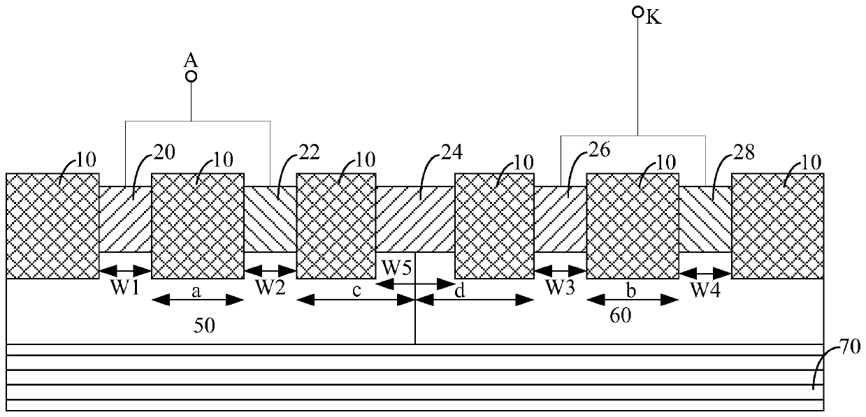
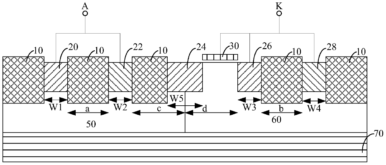
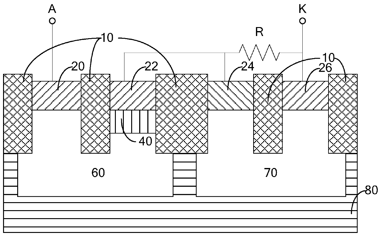
[0039] Figure 4 It is a circuit structure diagram of a preferred embodiment of a novel ESD protection structure of the present invention. Such as Figure 4 As shown, a novel ESD protection structure of the present invention includes an oxide layer (OX) 10, a first high-concentration N-type doping 20, a second high-concentration N-type doping 22, a second high-concentration P-type doping 2...


PUM


Abstract

The invention discloses a novel ESD protection structure and a realization method thereof. The novel ESD protection structure comprises a semiconductor substrate, a first N well, a second N well, a silicon-controlled rectifier and a diode structure, wherein the first N well and the second N well are generated in the semiconductor substrate; and the silicon-controlled rectifier is arranged in the first N well, and the diode structure is arranged in the second N well. In the invention, a maintenance voltage of an ESD protection structure hysteresis effect can be increased.

Description

technical field [0001] The invention relates to the technical field of semiconductor integrated circuits, in particular to a silicon-controlled rectifier type novel ESD protection structure and a realization method thereof. Background technique [0002] In the field of electrostatic (ESD, Electro-Static Discharge) protection design, Silicon Controlled Rectifier (SCR, Silicon Controlled Rectifier) ​​has been widely valued because of its strong ESD discharge capability and small parasitic capacitance, but there are two serious problems in this type of device Defects limit its application: the first defect is that the trigger voltage of the snapback effect (Snapback) is very high, because its trigger voltage is mainly limited by the reverse breakdown voltage of the N well to the P well; the second defect is the hysteresis effect (Snapback) The maintenance voltage is very low, which can easily lead to latch-up. [0003] In view of the defect of high trigger voltage, the industr...

Claims


Application Information

Patent Timeline
Patent Type & Authority Patents(China)
IPC IPC(8): H01L27/02
CPCH01L27/0255H01L27/0262H01L27/0296
Inventor 朱天志
Owner SHANGHAI HUALI MICROELECTRONICS CORP
Learn More