
Ripple wave compensating circuit for power supply device and compensating method therefor

A technology of power supply and ripple compensation, which is applied in high-efficiency power electronic conversion, instruments, electrical components, etc., and can solve problems such as AC/DC power supply instability

Inactive Publication Date: 2017-12-26
DELTA ELECTRONICS (THAILAND) PUBLIC CO LTD
View PDF13 Cites 1 Cited by
  • Summary
  • Abstract
  • Description
  • Claims
  • Application Information

AI Technical Summary

Problems solved by technology

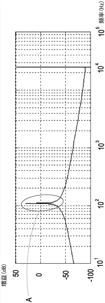
However, since the above-mentioned method of increasing the low-frequency gain of the input voltage of the LLC resonant conversion circuit is generated by multiplying the output voltage of the LLC resonant conversion circuit and the gain of the filter, the zero point and the pole point will actually change, so if the zero point and The pole-changed gain signal directly compensates the input voltage of the LLC resonant conversion circuit, which actually produces a significant phase impact, for example, Figure 1A The area marked A represents the increased gain of the input voltage of the LLC resonant conversion circuit at a frequency of about 100 Hz after being compensated by increasing the gain, but by Figure 1B The area marked A' can be known, when as Figure 1A While increasing the voltage gain, there is indeed a phase shock of about 90deg to about -90deg, and this huge phase shock will lead to instability of the AC / DC power supply

Method used


Image

  • Ripple wave compensating circuit for power supply device and compensating method therefor
  • Ripple wave compensating circuit for power supply device and compensating method therefor
  • Ripple wave compensating circuit for power supply device and compensating method therefor

Examples


Embodiment Construction

[0043] Some typical embodiments embodying the features and advantages of the present application will be described in detail in the description in the following paragraphs. It should be understood that the present application can have various changes in different aspects without departing from the scope of the present application, and that the description and drawings therein are considered to be illustrative in nature, rather than Used to limit this application.

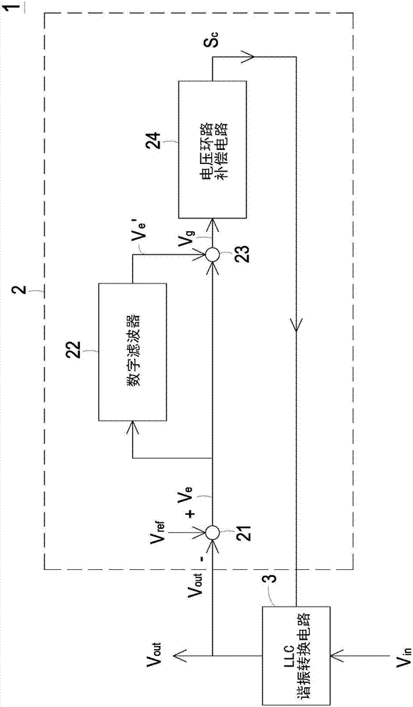
[0044] figure 2 It is a schematic circuit diagram of a ripple compensation circuit suitable for a power supply according to a preferred embodiment of the present application. Such as figure 2 As shown, the ripple compensation circuit 2 of the present application is applied in a power supply 1, wherein the power supply 1 can be but not limited to an AC / DC power supply, and the power supply 1 includes an LLC The resonant conversion circuit 3 , the LLC resonant conversion circuit 3 converts the received input volt...


PUM


Abstract

The application discloses a ripple wave compensating circuit for a power supply device and a compensating method therefor. The compensating method is suitable for the ripple wave compensating circuit for the power supply device. The power supply device comprises an LLC resonance oscillation converting circuit which is used for receiving input voltage and outputting output voltage. The compensating method comprises the following steps: (a) subtraction operation is performed on reference voltage and the output voltage, and therefore a first error signal is generated; (b) a digital filter is used for improving low frequency gain of the first error signal, and therefore a second error signal can be generated; (c) additive operation is performed on the first error signal and the second error signal, and therefore a modulation error signal is generated; (d) a compensation signal is generated correspondingly according to the modulation error signal so as to control the LLC resonance oscillation converting circuit, low frequency gain of LLC input voltage and response of a voltage loop compensation circuit can be increased, and the LLC resonance oscillation converting circuit is enabled to correspondingly output the output voltage for suppressing excessively low frequency ripple waves.

Description

technical field [0001] The present application relates to a ripple compensation circuit, in particular to a ripple compensation circuit and a compensation method suitable for a power supply. Background technique [0002] The power supply is a very commonly used electronic product in daily life. Almost all electrical devices are equipped with a power supply to supply power to the internal components or electronic components of the electrical device. Taking an AC / DC power supply as an example, it usually includes a power factor correction (PFC) circuit and an LLC resonant conversion circuit. Wherein, the power factor correction circuit receives an AC voltage, such as mains power, and performs power factor correction on the AC voltage to output a transitional DC voltage. The LLC resonant conversion circuit receives the transitional DC voltage, and converts the received transitional DC voltage into output DC voltages of different voltage levels in a resonant manner. [0003] H...

Claims


Application Information

Patent Timeline
IPC IPC(8): H02M1/14H02M3/335
CPCH02M1/143H02M3/335H02M1/0012Y02B70/10
Inventor 多米尼克·莱因哈特·班黎克
Owner DELTA ELECTRONICS (THAILAND) PUBLIC CO LTD
Learn More