
Damping disk progressive die of automobile clutch

A technology of progressive die and shock-absorbing disc, applied in the direction of feeding device, vehicle parts, forming tools, etc., to achieve the effect of improving utilization rate, reducing mold usage, improving production and processing speed and parts production accuracy

Pending Publication Date: 2017-12-29
SHAANXI WEIHE TOOLS CO LTD
View PDF9 Cites 0 Cited by
  • Summary
  • Abstract
  • Description
  • Claims
  • Application Information

AI Technical Summary

Problems solved by technology

[0005] In view of the above technical problems, the present invention intends to provide a progressive die for automobile clutch damping discs, which can meet the heat treatment requirements of automobile clutch damping discs and the technical requirements of continuous rotation of the key structure under the action of torsional force without cracks or fractures, and realize a single mold To meet the requirements of producing two different products, and replace the original single-process mold, improve the production processing speed and processing accuracy, improve the punching speed and material utilization rate, and reduce the demand for the number of molds

Method used


Image

  • Damping disk progressive die of automobile clutch
  • Damping disk progressive die of automobile clutch
  • Damping disk progressive die of automobile clutch

Examples


Embodiment Construction

[0030] The implementation process of the present invention will be further described in detail below in conjunction with the accompanying drawings.

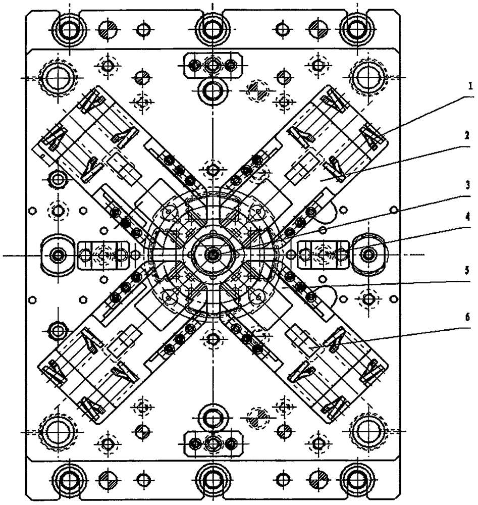
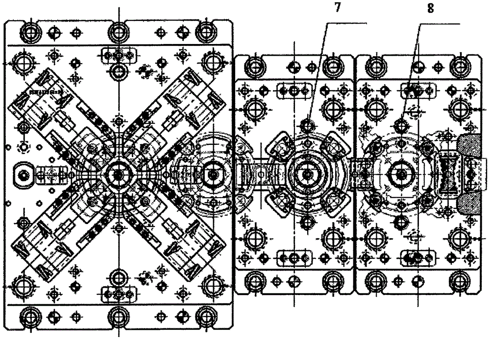
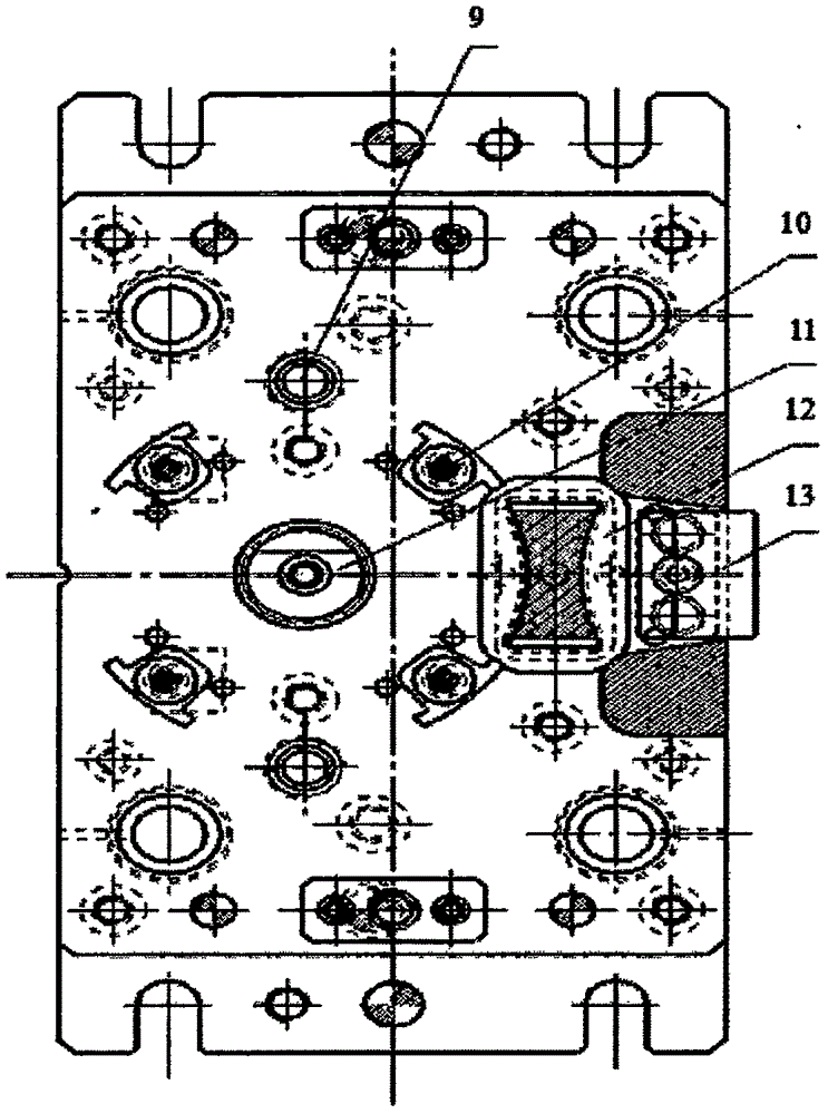
[0031] Such as Figure 1 to Figure 3 Shown: a progressive die for an automobile clutch damping disc, including a progressive die body, characterized in that: it also includes a positioning guide 3 positioned at the progressive die body, arranged in an X shape with the positioning guide 3 4 rectangular oblique sliders 2 deployed as the center, the oblique slider return spring 1 at the end of each oblique slider 2, the bending die 5 at the root of each oblique slider 2, the The inclined iron 6 between the oblique slider return spring 1 in the middle section of each oblique slider 2 and the bending die 5, and the two floating blocks 4 located on both sides of the positioning guide head 3, the The inclined slider return spring 1 can utilize its spring force to reset the inclined slider 2 and the bending die 5, and the recovery time ...


PUM


Abstract

The invention belongs to the automobile industrial field and relates to a damping disk progressive die of an automobile clutch. The damping disk progressive die of the automobile clutch comprises a locating guide head, four inclined sliding blocks forming a rectangle, inclined sliding block reset springs, bending female dies, inclined iron pieces and two flotation blocks, wherein the locating guide head is located on a progressive die body, the four inclined sliding blocks are arranged in an X shape and spread with the locating guide head as the center, each inclined sliding block reset spring is located at the tail end of the corresponding inclined sliding tail end, each bending female die is located at the root portion of the corresponding inclined sliding block, each iron piece is located between the middle section of each inclined sliding block and arranged between the corresponding inclined sliding block reset spring and the corresponding bending female die, and the two floating blocks are located on the two sides of the locating guide head. The inclined sliding block reset springs can utilize the spring force to enable the inclined sliding block and the bending female dies to conduct reset. The recovery time of the inclined sliding block reset springs is shorter than the rising time of the floatation blocks. The damping disk progressive die of the automobile clutch meets the heat treatment demand of a damping disk of the automobile clutch and meets the requirement that a continuous rotation key structure is free of cracks and fracture under the action of twisting force, the production and machining speed and the machining accuracy are improved, the punching speed and the material utilization rate are improved, and the number of needed dies is reduced.

Description

technical field [0001] The invention belongs to the field of automobile industry and relates to the processing of a progressive die, in particular to a progressive die for an automobile shock-absorbing disc. Background technique [0002] With the development of my country's automobile industry in recent years, automobile manufacturing technology has also been greatly improved. Among them, the automobile clutch is an important part of the automobile transmission system, which shoulders important functions such as power transmission, shock absorption and overload prevention. At present, most clutch parts rely on mold stamping processing, and there is a great demand for molds; at the same time, most of the molds currently used for processing, including punching dies, punching dies, and bending dies, are all special-purpose. Single-process low-end molds are inconvenient to use and time-consuming. [0003] The vibration damping disc is a key part of the automobile clutch. After...

Claims


Application Information

Patent Timeline
Patent Type & Authority Applications(China)
IPC IPC(8): B21D37/10B21D43/00B21D53/88
CPCB21D37/10B21D43/003B21D53/88
Inventor 李海涛何学勇高宏庭李剑敏吕平华张相哲
Owner SHAANXI WEIHE TOOLS CO LTD
Learn More