Cooling roller for turbulence high heat exchange amorphous strip production

A technology for amorphous strips and cooling rolls, which is applied in the field of amorphous strip production, can solve the problems of large differences in axial temperature distribution and the degree of amorphousness in the middle of the strip, so as to promote heat transfer in the center of the roller sleeve and reduce Effect of temperature gradient, improving heat exchange efficiency and effectiveness

Inactive Publication Date: 2017-12-29
浙江艾默可科技有限公司
View PDF1 Cites 1 Cited by
  • Summary
  • Abstract
  • Description
  • Claims
  • Application Information

AI Technical Summary

Problems solved by technology

[0005] The present invention aims to solve the above-mentioned problems existing in the cooling rolls of the prior art, and provides a kind of ingenious structure, good heat exchange effect, which can effectively solve the large difference in the axial temperature distribution of the roll sleeve in the contact area with t

Method used


Image

  • Cooling roller for turbulence high heat exchange amorphous strip production
  • Cooling roller for turbulence high heat exchange amorphous strip production

Examples


Embodiment Construction

[0021] The present invention will be further described below in conjunction with the accompanying drawings and specific embodiments.

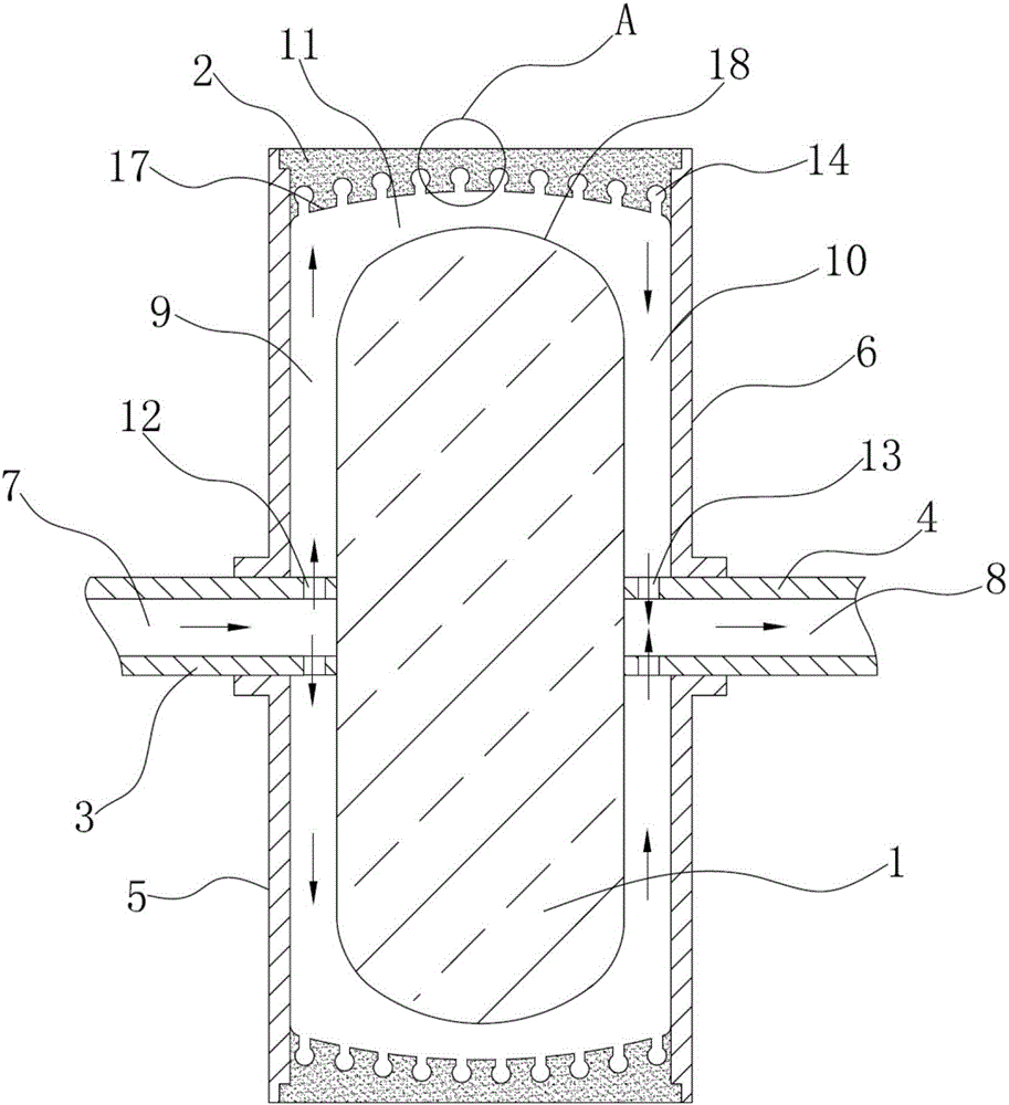
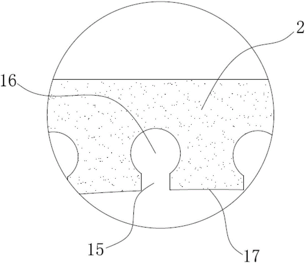
[0022] Such as figure 1 , figure 2 A cooling roll for the production of turbulent-flow strong heat-exchanging amorphous strip is shown, including a roll core 1, a roll sleeve 2, a left main shaft 3, a right main shaft 4, a left cover 5 and a right cover 6, a left cover, The right cover plates are respectively arranged on both sides of the roller core and are fixedly connected by the roller sleeves sleeved on the circumferential outer side of the roll core. The left main shaft passes through the left cover plate and is fixedly connected with it. The main shaft passes through the right cover plate and is rotatably connected with the right cover plate. The right main shaft is provided with a cooling medium outflow channel 8, and the spaces between the left cover plate, the right cover plate and the roller core respectively form the cooling mediu...


PUM


Abstract

The invention discloses a cooling roll for the production of turbulent flow and strong heat exchange amorphous strip, which comprises a roll core, a roll sleeve, a left main shaft, a right main shaft, a left cover plate and a right cover plate, and a cooling medium enters a channel inside the left main shaft. There is a cooling medium outflow channel in the right spindle, the space between the left cover plate, the right cover plate and the roller core respectively forms the left circulation channel of the cooling medium, the right circulation channel of the cooling medium, and the space between the roller sleeve and the roller core forms a turbulent flow and strong heat exchange There is a cooling medium radial outlet in the left main shaft, and a cooling medium radial inlet in the right main shaft. The thickness of the roller sleeve and the depth of the turbulent heat exchange channel increase from the longitudinal centerline of the roller sleeve to both sides. A plurality of annular grooves for turbulent heat exchange are arranged at intervals in the width direction of the cover, and the annular grooves for turbulent heat exchange include a notch section with a rectangular cross-section and a groove bottom section with a spherical cross-section. The heat exchanging effect of the invention is good, and the problem of large difference in axial temperature distribution of the roller sleeve in the contact area with the strip, which leads to the depression in the middle of the strip and the poor degree of amorphousness in the middle of the strip is solved.

Description

technical field [0001] The invention relates to the technical field of production of amorphous strips, in particular to a cooling roll for production of amorphous strips with turbulent flow and strong heat exchange. Background technique [0002] The working principle of the amorphous strip making machine is: the molten amorphous master alloy solution in the crucible is sprayed onto the fast-rotating water-cooled strip roller through the gap at the bottom of the crucible, and the alloy solution is strongly cooled and thrown out to form an amorphous strip. Crystal ribbon. [0003] During the strip spraying process, the strip will have middle depressions and poor amorphousness, mainly because the molten alloy is sprayed onto the high-speed rotating cooling roll through the nozzle, and an alloy molten pool is formed between the nozzle and the roll surface. , within the width range where the molten pool is in contact with the roll surface, there is a temperature gradient field s...

Claims


Application Information

Patent Timeline
IPC IPC(8): B22D11/06
CPCB22D11/06
Inventor 钱建军
Owner 浙江艾默可科技有限公司
Why Eureka
Try Eureka