Torsional Damper With Angular-Dependent Friction Damping Device

A torsional shock absorber and friction device technology, which is applied in the direction of shock absorbers, friction clutches, springs/shock absorbers, etc., can solve problems such as radial structural space limitations and wear volume limitations, and achieve the effect of increasing friction torque

Inactive Publication Date: 2017-12-29
ZF FRIEDRICHSHAFEN AG
View PDF7 Cites 4 Cited by
  • Summary
  • Abstract
  • Description
  • Claims
  • Application Information

AI Technical Summary

Problems solved by technology

As a result, the wear volume is also limited, since the radial construction space is also limited

Method used


Image

  • Torsional Damper With Angular-Dependent Friction Damping Device
  • Torsional Damper With Angular-Dependent Friction Damping Device
  • Torsional Damper With Angular-Dependent Friction Damping Device

Examples


Embodiment Construction

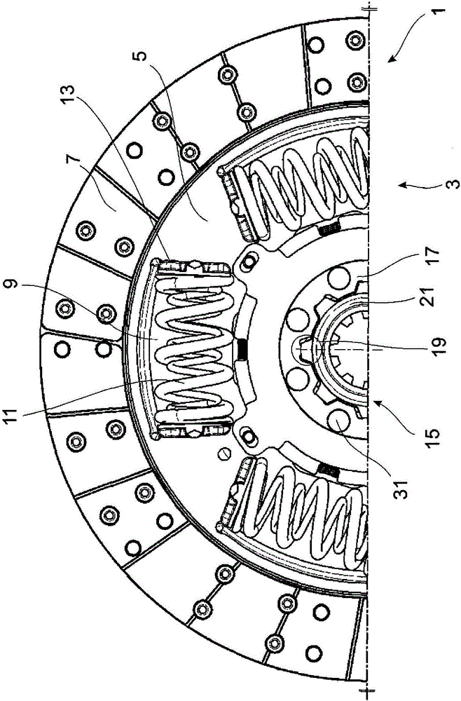
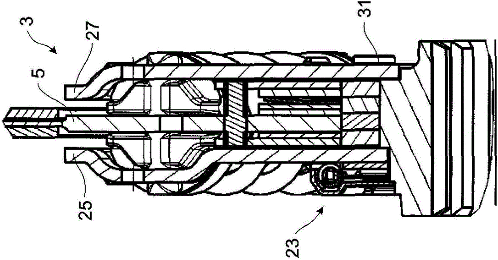
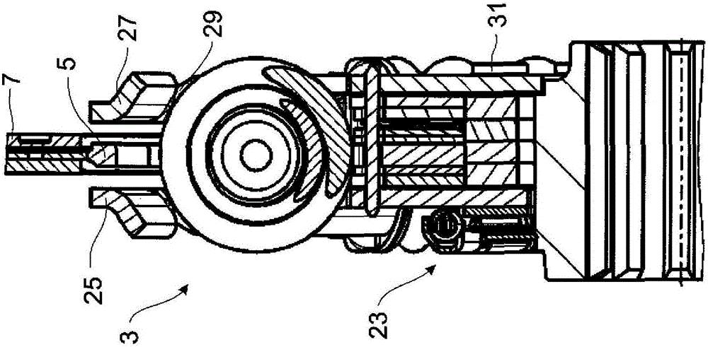
[0027] figure 1 A front view of a partially assembled clutch disk 1 with a torsional vibration damper 3 is shown. In principle, the torsional vibration damper can also be used outside the clutch disc. combine figure 2 and image 3 It can be clearly seen that the torsional vibration damper 3 has a torque input disk 5 which carries the friction lining 7 . On this torque input disc 5 , for example, the torque of the drive motor is transmitted via a clutch housing (not shown) to the friction linings.

[0028] The torque input disc 5 has a window-like recess 9 in which at least one spring energy store 11 , for example a helical compression spring, is arranged. In this example, a support disk 13 is inserted between the end turn of the helical compression spring 11 and the notch 9 .

[0029] The torque input disk 5 is centered on its inner diameter relative to the torsional vibration damper hub 15 . By way of example, the torsional damper hub 15 is designed as a split, in whic...


PUM


Abstract

The invention relates to a torsional damper provided with at least one torque input disk and at least one torque output disk. The torque input disc relative to the torque output disc can move in the circumferential direction against the force of at least one spring accumulator; the relative movement is damped by a friction device which generates a smaller frictional torque in a first oscillating angle range than in a second oscillating angle range in that the friction device has at least two mutually rotatable pairs of friction rings, which are activated by the oscillation angle, wherein a first group of friction rings in the circumferential direction are fixed to the torque output part - and a second group of friction rings in the circumferential direction in the first swing angle range are relatively movable to the torque input disk and is mounted to the torque output disk - and in the second swing angle range, the second group of friction rings in the circumferential direction in a driving in the second oscillation angle range, a relative movement takes place in the circumferential direction between the torque output disk and the second friction ring and a relative movement in the circumferential direction between the torque input disk and the first friction ring group.

Description

technical field [0001] The invention relates to a torsional vibration damper with a swivel angle-dependent friction device. Background technique [0002] The problem of premature failure is not uncommon with traditional friction devices. Most friction devices operate with a constant friction torque / constant damping over the entire characteristic curve of the torsional vibration damper or are adapted to a characteristic curve region or a spring stage. For this purpose, for example in DE 10 2007 006 381 A1, the control web engages in the spring window or at least has a control edge for the spring. However, the magnitude of the required friction torque is only determined by the required damping of the drive train resonance in the individual gears of the gearbox. The greater the resonance, the greater the required damping (=friction torque) and thus the greater the load on the friction device. In the usual sense, a load is a greater force (mostly a coil spring) in the contact...

Claims


Application Information

Patent Timeline
Patent Type & Authority Applications(China)
IPC IPC(8): F16D3/14F16D13/64F16F15/12F16F15/121F16F15/123
CPCF16D3/14F16D13/64F16F15/12F16F15/1215F16F15/123F16D13/68F16F15/1295F16D2300/22F16D3/12F16D13/644F16F15/12353F16F15/129F16F2222/04F16F2232/02
Inventor D·比尔
Owner ZF FRIEDRICHSHAFEN AG
Why Eureka
Try Eureka