Method of identifying faulted component in automotive system

A technology for faulty components and automobiles, applied in the testing of machine/structural components, testing of vehicles, vibration measurement in solids, etc., to achieve the effect of improving customer satisfaction

Inactive Publication Date: 2017-12-29
GM GLOBAL TECH OPERATIONS LLC
View PDF7 Cites 5 Cited by
  • Summary
  • Abstract
  • Description
  • Claims
  • Application Information

AI Technical Summary

Problems solved by technology

[0008] So in general, current maintenance procedures are based on the experience of the maintenance personnel and are not always effective

Method used


Image

  • Method of identifying faulted component in automotive system
  • Method of identifying faulted component in automotive system
  • Method of identifying faulted component in automotive system

Examples


Embodiment Construction

[0042] Exemplary embodiments will now be described with reference to the accompanying drawings, not intended to limit application and use.

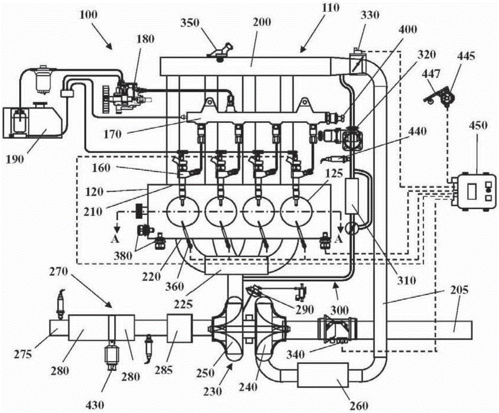
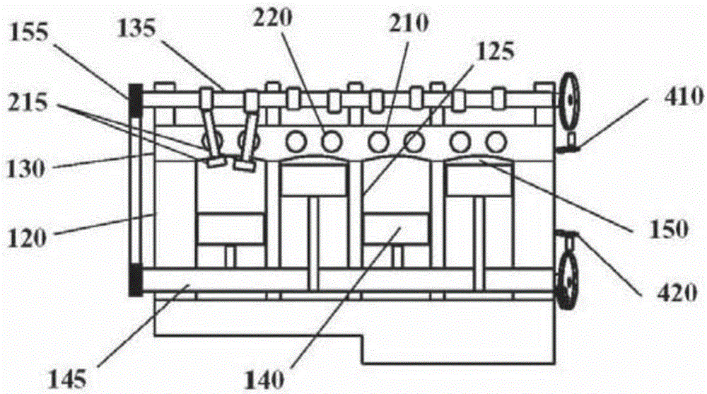
[0043] Some embodiments may include such as figure 1 and figure 2 The illustrated turbocharged automotive system 100 includes an internal combustion engine (ICE) 110 having an engine block 120 defining at least one cylinder 125 having a piston 140 coupled to rotate a crankshaft 145 . Cylinder head 130 cooperates with piston 140 to define combustion chamber 150 . A fuel and air mixture (not shown) is placed in combustion chamber 150 and ignited, resulting in thermally expanding exhaust gases that cause reciprocation of piston 140 . Fuel is provided by at least one fuel injector 160 and air is provided through at least one air intake 210 . Fuel is provided to fuel injector 160 at high pressure from fuel rail 170 in fluid communication with high pressure fuel pump 180 which increases the pressure of fuel received from fuel source 190 . ...


PUM


Abstract

The invention provides a method of identifying a faulted component (700) in an automotive system (100) including an internal combustion engine (110) managed by an Electronic Control Unit (450). The internal combustion engine (110) is operated according to a predefined detection routine (680). A noise signal (640) emitted by the activated internal combustion engine (110) is recorded in a data carrier (460) or memory system. The recorded noise signal (640) is analyzed by a signal treatment algorithm (650) to determine a plurality of vibration modes (660) of the automotive system (100) from the noise signal (640); the amplitude of the noise signal (640) is compared at each vibration mode (660) with an acceptable amplitude threshold (670). A faulted component (700) of the automotive system (100) is determined if the amplitude of the correspondent vibration mode is greater than the acceptable amplitude threshold.

Description

technical field [0001] The technical field relates to methods of identifying faulty components in automotive systems. Background technique [0002] Automotive systems include multiple interconnected devices such as internal combustion engines, turbocharging systems, exhaust gas recirculation (EGR) systems, aftertreatment systems, and various other components such as conduits, valves, sensors, fuel injectors, and the like. [0003] Due to the complexity of current automotive systems, in the event of a failure, it is not always easy and straightforward to identify the specific component that is not functioning properly. [0004] Some faults may be determined by receiving data from sensors of the automotive system, comparing the data to predefined thresholds or ranges, and reporting a fault code if the measured data does not meet these predefined thresholds or ranges. [0005] However, many faults may not be easily detected by using on-board sensors. [0006] In addition, man...

Claims


Application Information

Patent Timeline
Patent Type & Authority Applications(China)
IPC IPC(8): G01M17/007G01M7/02
CPCG01M7/00G01M17/007F02D41/10F02D2041/288F02D2200/025Y02T10/40F02D41/22G01H1/00G01M15/04G01M15/12F02D35/027F02D41/26
Inventor M.梅利斯F.帕里西E.曼塔N.科斯塔M.贝卢肖
Owner GM GLOBAL TECH OPERATIONS LLC
Why Eureka
Try Eureka