Focusing endoscope

An endoscope and focusing technology, which is applied in the field of endoscopes, can solve problems such as inconvenient use, troublesome use, and restrictions on working conditions, and achieve the effects of focusing or zooming functions, simple and convenient operation, and miniaturization

Pending Publication Date: 2017-12-29
SHANGHAI EDA PHOTOELECTRONICS TECH CO LTD
View PDF1 Cites 3 Cited by
  • Summary
  • Abstract
  • Description
  • Claims
  • Application Information

AI Technical Summary

Problems solved by technology

However, the correct replacement head must be selected for each use, otherwise the endoscope has to be pulled out from the working condition, and then inserted for observation after replacing the replacement head, which brings great inconvenience to the use
It is even more troublesome when you encounter several different working conditions at one time
Moreover, an endoscope needs to be equipped with replacement heads with different depth of field ranges, which is expensive
[0006] There is also a solution, such as a zoom endoscope provided by CN201620590716 and US7961401B1. The size of the zoom structure is relatively large, which is not conducive to the miniaturization of the diameter of the insertion part of the endoscope, thus greatly restricting the working conditions
Moreover, how to achieve reliable zoom operation when the insertion tube of the flexible endoscope is bent, the current solution is to use a built-in micro-motor at the end of the endoscopic lens, which is not only costly, but also limited by the technical development of micro-motors. It is difficult to reduce the diameter of the insertion part of the endoscope

Method used


Image

  • Focusing endoscope
  • Focusing endoscope
  • Focusing endoscope

Examples


Embodiment Construction

[0060] The present invention will be described in detail below in conjunction with specific embodiments. The following examples will help those skilled in the art to further understand the present invention, but do not limit the present invention in any form. It should be noted that those skilled in the art can make several changes and improvements without departing from the concept of the present invention. These all belong to the protection scope of the present invention.

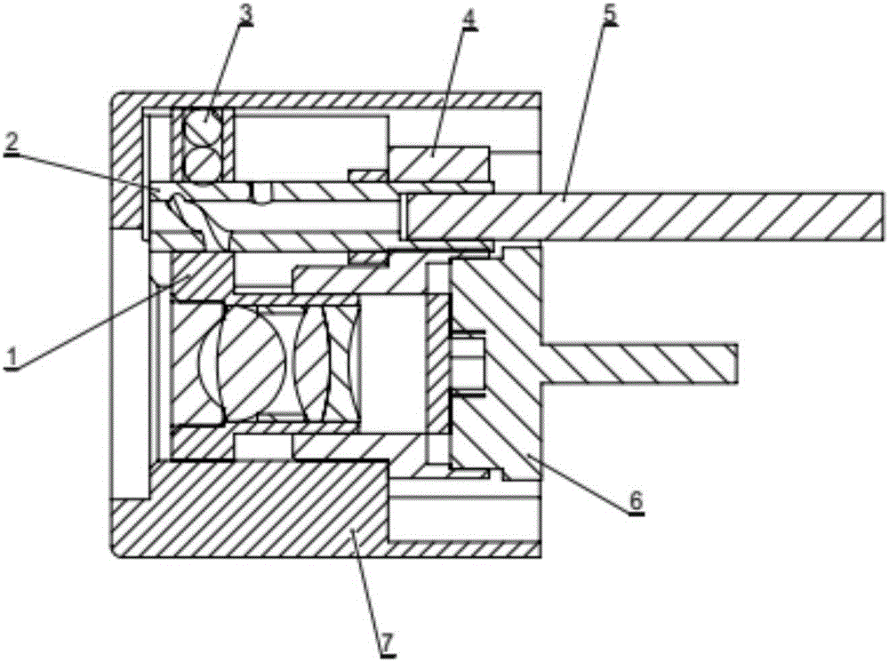
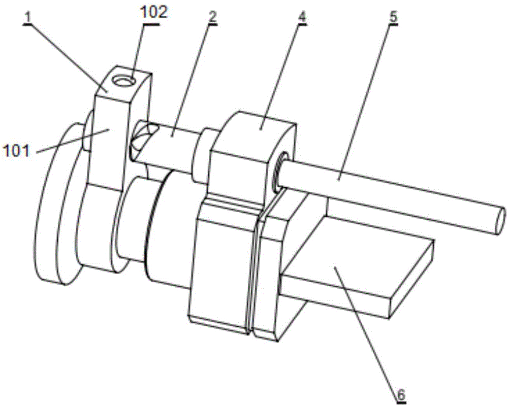
[0061] The present invention provides a focusing endoscope, which includes an objective lens housing 1, a focusing screw 2, a camera seat 4, a rotating element 5 and a focusing control part, wherein,

[0062] The objective lens case 1 and the camera seat 4 are arranged oppositely, and the convex portion of the objective lens case 1 is movably arranged on the camera seat 4;

[0063] The focusing screw 2 passes through the objective lens housing 1 and the camera seat 4;

[0064] One end of the rotating e...


PUM


Abstract

The invention provides a focusing endoscope, and the endoscope comprises an objective lens case, a focusing screw rod, a camera holder, a rotating element, and a focusing operating part. The objective lens case is arranged to be opposite to the camera holder, and a projection part of the objective lens case is movably disposed on the camera holder. The focusing screw rod passes through the objective lens and the camera holder. One end of the rotating element is connected with the focusing screw rod, and the other end of the rotating element is connected with the focusing operating part. When the focusing operating part drives the rotating element to rotate, the rotating element drives the focusing screw rod to rotate. When the focusing screw rod rotates, the objective lens case is driven to move. According to the invention, the endoscope can achieve the moving operation of a lens or a lens group under the condition that an insertion pipe of a flexible endoscope is bent, thereby achieving the focusing or zooming function, and achieving the miniaturization of the diameter of an insertion part of the endoscope.

Description

technical field [0001] The invention relates to the technical field of endoscopes, in particular to a focusing endoscope. Background technique [0002] Endoscope is a precision instrument combined with fiber optics and optics, precision machinery and electronic technology. It has a wide range of uses and important roles in various fields of national economy such as medical treatment, industry and military. [0003] When the endoscope is in use, the distance between the observed object and the endoscope lens end is very different under different working conditions. Sometimes it needs to be observed very close, and sometimes it needs to be observed from a long distance. [0004] The head end of the endoscope in the prior art, because its built-in optical system is set, its depth of field is adjusted to different depth of field ranges during assembly, but it is fixed after adjustment and cannot be changed again. It cannot be changed while in use. Therefore, at present, optic...

Claims


Application Information

Patent Timeline
Patent Type & Authority Applications(China)
IPC IPC(8): G02B23/24G02B7/04
CPCG02B7/04G02B23/243
Inventor 孔维彪余宝国孔瑞煜张民言李承玖陈祝言陆文浩
Owner SHANGHAI EDA PHOTOELECTRONICS TECH CO LTD
Why Eureka
Try Eureka