Mechanical arm and substrate grabbing method

A technology of robotic arms and manipulators, applied in the directions of manipulators, conveyor objects, electrical components, etc., can solve problems such as scratching the substrate, and achieve the effect of ensuring the safety of picking and placing and reducing the risk of scratches

Active Publication Date: 2017-12-29
ZING SEMICON CORP
View PDF5 Cites 3 Cited by
  • Summary
  • Abstract
  • Description
  • Claims
  • Application Information

AI Technical Summary

Problems solved by technology

[0004] The purpose of the present invention is to provide a method for grabbing a robot arm and a substrate, so as to improve the problem of scratching the substrate when the robot arm picks and places the substrate

Method used


Image

  • Mechanical arm and substrate grabbing method
  • Mechanical arm and substrate grabbing method
  • Mechanical arm and substrate grabbing method

Examples


Embodiment 1

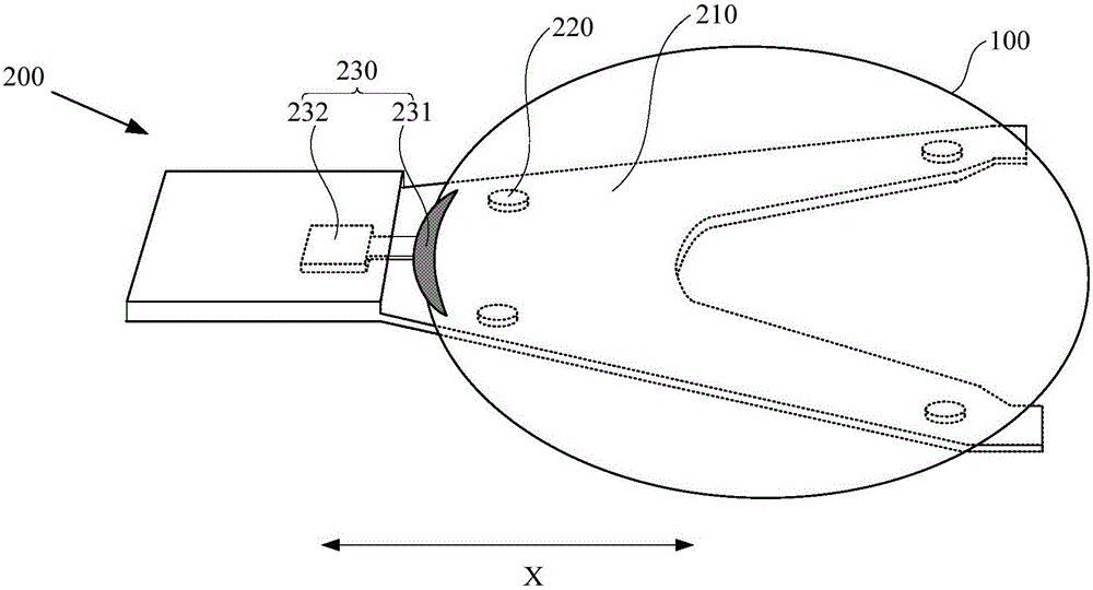
[0036] image 3 It is a schematic structural diagram of the mechanical arm in Embodiment 1 of the present invention, Figure 4 It is a schematic structural diagram of a robot arm carrying a substrate in Embodiment 1 of the present invention. In this embodiment, the substrate is a wafer. combine image 3 and Figure 4 As shown, the robotic arm 200 includes: a robotic disc 210 , a contact pad 220 and an adsorption device 230 disposed on the robotic disc 210 . Wherein, the manipulator plate 210 carries the weight of the entire substrate 100, which has a certain thickness c1; the contact pad 220 is in contact with the substrate 100 and supports the substrate to reduce the contact area between the substrate 100 and the manipulator plate 210, and in consideration On the basis of the deformation of the substrate 100, the contact pad 220 also needs to have a certain thickness c2; the adsorption device 230 is used to adsorb and fix the substrate 100 to prevent the substrate from sha...

Embodiment 2

[0043] Figure 5 It is a structural schematic diagram of the robot arm in the second embodiment of the present invention. Such as Figure 5 As shown, the difference from Embodiment 1 is that in this embodiment, the adsorption device 230 ′ is fixed on the manipulator plate 210 , and fixes the substrate 100 by adsorbing the lower surface of the substrate 100 , wherein the adsorption The thickness of device 230 ′ is less than the thickness of contact pad 220 . That is, in this embodiment, since the adsorption device 230' is used to adsorb the lower surface of the substrate 100, when the contact pad 220 supports the substrate 100, the adsorption device 230' is correspondingly located below the substrate 100, therefore Therefore, fixing the adsorption device 230 ′ directly on the manipulator plate 210 can still achieve the function of absorbing the substrate 100 , thus making the structure of the robot arm 200 ′ simpler. In addition, since the thickness of the adsorption device ...


PUM


Abstract

The invention provides a mechanical arm and a substrate grabbing method. The mechanical arm is used for fetching and placing a substrate in a substrate storage region. The mechanical arm comprises a mechanical arm disc, a contact pad and an absorption device, wherein the contact pact and the absorption device are disposed on the mechanical arm disc. Moreover, when the mechanical arm is used for fetching and placing the substrate, the thickness of the mechanical arm in the substrate storage region is the sum of the thickness of the mechanical arm disc and the thickness of the contact pad. Compared with a conventional mechanical arm, the mechanical arm provided by the invention is small in occupied space in the substrate storage region when the mechanical arm is used for fetching and placing the substrate, thereby reducing the risk in scraping the substrate on the condition that the original precision of the mechanical arm is not changed.

Description

technical field [0001] The invention relates to the technical field of semiconductors, in particular to a method for grabbing a robot arm and a substrate. Background technique [0002] Since the robotic arm can receive instructions and perform corresponding actions according to the received instructions, in the field of semiconductor manufacturing, robotic arms are usually used to transfer substrates between substrate storage areas and processing equipment to achieve automated production. [0003] For example, during the processing of the wafer, the wafer is placed in a cassette, and a robot arm is used to grab the wafer in the cassette and transfer the wafer to the processing equipment. figure 1 It is a structural schematic diagram of a robotic arm grabbing a wafer located in a cassette in the prior art, such as figure 1 As shown, the cassette 30 is provided with a plurality of slots 31 for carrying wafers. When the robot arm 20 is picking up and placing wafers, it needs t...

Claims


Application Information

Patent Timeline
Patent Type & Authority Applications(China)
IPC IPC(8): H01L21/677H01L21/683B25J15/06
CPCB25J15/0683H01L21/67742H01L21/6838
Inventor 赵旭良金嵩
Owner ZING SEMICON CORP
Why Eureka
Try Eureka