Umbrella-type hydro-generator shaft insulating structure

A technology of hydro-generator and insulating structure, which is applied in electrical components, electromechanical devices, electric components, etc., can solve the problems of difficult online real-time monitoring, etc., and achieve the effects of high rigidity, reduced difficulty, and prevention of accidents.

Pending Publication Date: 2017-12-29
DONGFANG ELECTRIC MACHINERY
View PDF7 Cites 2 Cited by
  • Summary
  • Abstract
  • Description
  • Claims
  • Application Information

AI Technical Summary

Problems solved by technology

At the same time, the insulation of the guide bearing requires multiple insulations, including the temperature measuring resistance of the guide bearing, and it is not easy to realize online real-time monitoring

Method used


Image

  • Umbrella-type hydro-generator shaft insulating structure
  • Umbrella-type hydro-generator shaft insulating structure
  • Umbrella-type hydro-generator shaft insulating structure

Examples


Embodiment 1

[0029] As a preferred embodiment of the present invention, this embodiment discloses:

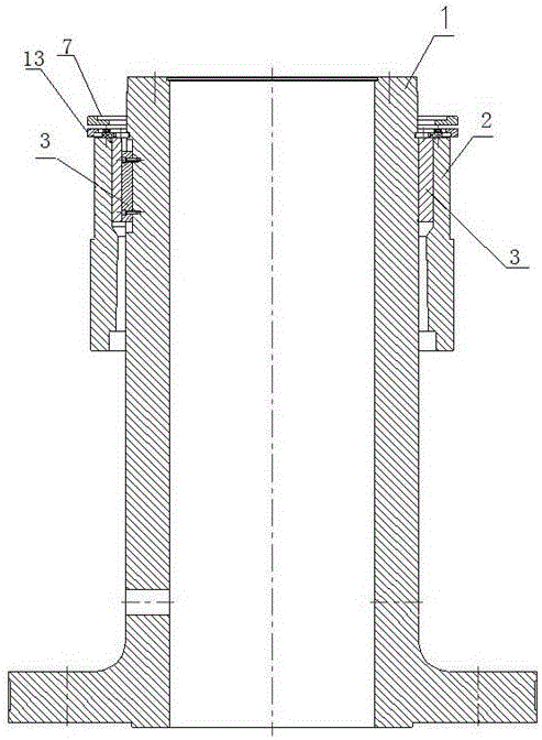
[0030] An umbrella-type hydraulic generator shaft insulation structure, including an upper shaft 1 and a sliding rotor 2, a first insulating layer 4, a conductive layer 5 and a second insulating layer 6 are arranged between the upper shaft 1 and the sliding rotor 2, the The second insulating layer 6 is wrapped around the conductive layer 5 . In this embodiment, the first insulating layer 4 and the second insulating layer 6 can be made of conventional insulating materials, such as insulating pads.

Embodiment 2

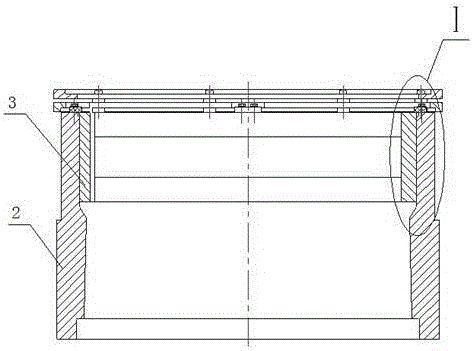
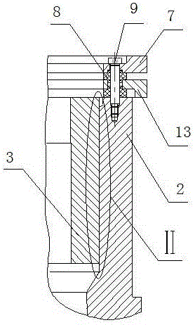
[0032] As another preferred embodiment of the present invention, this embodiment discloses: an umbrella type hydroelectric generator shaft insulation structure, including an upper end shaft 1 and a sliding rotor 2, and a second An insulating layer 4 , a conductive layer 5 and a second insulating layer 6 , the second insulating layer 6 wraps around the conductive layer 5 . In this embodiment, the first insulating layer 4 and the second insulating layer 6 can be selected from conventional insulating materials, such as insulating pads; also include an upper measuring ring 7 and a lower measuring ring 13, the upper measuring ring 7 and the lower measuring ring 13 is fixed on the sliding rotor 2 through insulating pads 8 and bolts; the conductive layer 5 is connected to the lower measuring ring 13 through lead wires 10; the sliding rotor 2 is electrically connected to the upper measuring ring 7 through bolts.

Embodiment 3

[0034] As another preferred embodiment of the present invention, this embodiment discloses:

[0035] An umbrella-type hydraulic generator shaft insulation structure, including an upper shaft 1 and a sliding rotor 2, a first insulating layer 4, a conductive layer 5 and a second insulating layer 6 are arranged between the upper shaft 1 and the sliding rotor 2, the The second insulating layer 6 is wrapped on the conductive layer 5; a sleeve 3 is also arranged between the upper shaft 1 and the sliding rotor 2, and the sleeve 3 is arranged between the first insulating layer 4 and the upper shaft 1 ; The first insulating layer 4 is wrapped around the sleeve 3; the sleeve 3 is connected with the upper shaft 1 through a key; the sliding rotor 2 and the sleeve 3 are connected together through an interference fit.

[0036] In this embodiment, the first insulating layer 4, the conductive layer 5 and the second insulating layer 6 can be stacked layer by layer or wrapped layer by layer. Wh...


PUM


Abstract

The invention discloses an umbrella-type hydro-generator shaft insulating structure, and relates to the technical field of hydro-generators. The structure comprises an upper shaft and a sliding rotor, and a first insulating layer, a conductive layer and a second insulating layer are disposed between the upper shaft and the sliding rotor. The second insulating layer is disposed on the conductive layer in a wrapping manner. The structure solves a shaft current problem of a generator set in the prior art, also improves the support stiffness of a generator set shaft system, improves the operation stability of the generator set, and reduces the vibration and noise of the generator set.

Description

technical field [0001] The invention relates to the technical field of hydroelectric generators, in particular to an umbrella-type hydroelectric generator shaft insulation structure. Background technique [0002] As we all know, due to the asymmetry of the magnetic circuit around the motor shaft, the rotor does not run concentrically, or due to electrostatic charging caused by the oil film with insulating properties in the bearing, and the base with seams or improper core laminations, the shaft is magnetized or damaged. Induced pulse flux, which will make the shaft-bearing-bottom plate (or frame) circuit have shaft voltage and generate shaft current. The main influence of the shaft current is the damage of the bearing surface caused by the arc across the bearing oil film. Because the current flows through the contact point and concentrates on the extremely small contact area, when the local oil film loses its insulation effect, the current density is very high, and arc and a...

Claims


Application Information

Patent Timeline
Patent Type & Authority Applications(China)
IPC IPC(8): H02K5/16
CPCH02K5/16
Inventor 黄智欣何伟邓斌刘小松
Owner DONGFANG ELECTRIC MACHINERY
Why Eureka
Try Eureka