Method and device for wireless communication
A wireless signal and channel matrix technology, applied in the fields of CSI feedback and multi-antenna transmission, can solve the problem that the accuracy is difficult to meet the needs of MU-MIMO transmission.
- Summary
- Abstract
- Description
- Claims
- Application Information
AI Technical Summary
Problems solved by technology
Method used
Image
Examples
Embodiment 1
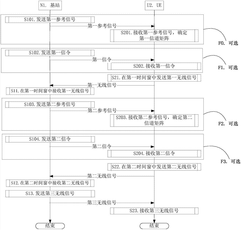
[0178] Embodiment 1 illustrates the flow chart of downlink transmission, as attached figure 1 shown. attached figure 1 In , the base station N1 is the serving cell maintenance base station of the UE U2. attached figure 1 , the steps in box F0, box F1, box F2 and box F3 are optional.
[0179] For N1, send the first reference signal in step S101; send the first signaling in step S102; receive the first wireless signal in step S11; send the second reference signal in step S103; send the second Signaling: receiving the second wireless signal in step S12; sending the third wireless signal in step S13.
[0180] For U2, receive the first reference signal in step S201, determine the first channel matrix; receive the first signaling in step S202; send the first wireless signal in the first time window in step S21; receive in step S203 The second reference signal is to determine a second channel matrix; receive second signaling in step S204; send a second wireless signal in a secon...
Embodiment 2
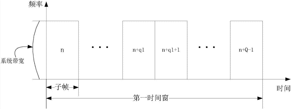
[0227] Embodiment 2 illustrates the schematic diagram of the first time window, as attached figure 2 shown.
[0228] In Embodiment 2, the first time window includes Q consecutive subframes, and the corresponding subframe indexes are {n, n+1, . . . , n+Q-1}.
[0229] The first parameter is sent in the first subframe in the first time window, that is, subframe n.
[0230] As a sub-embodiment 1 of Embodiment 2, the UE reports the first parameter only once in the first time window.
[0231] As a sub-embodiment 2 of Embodiment 2, the first information is sent in subframe n+q1 in the first time window.
Embodiment 3
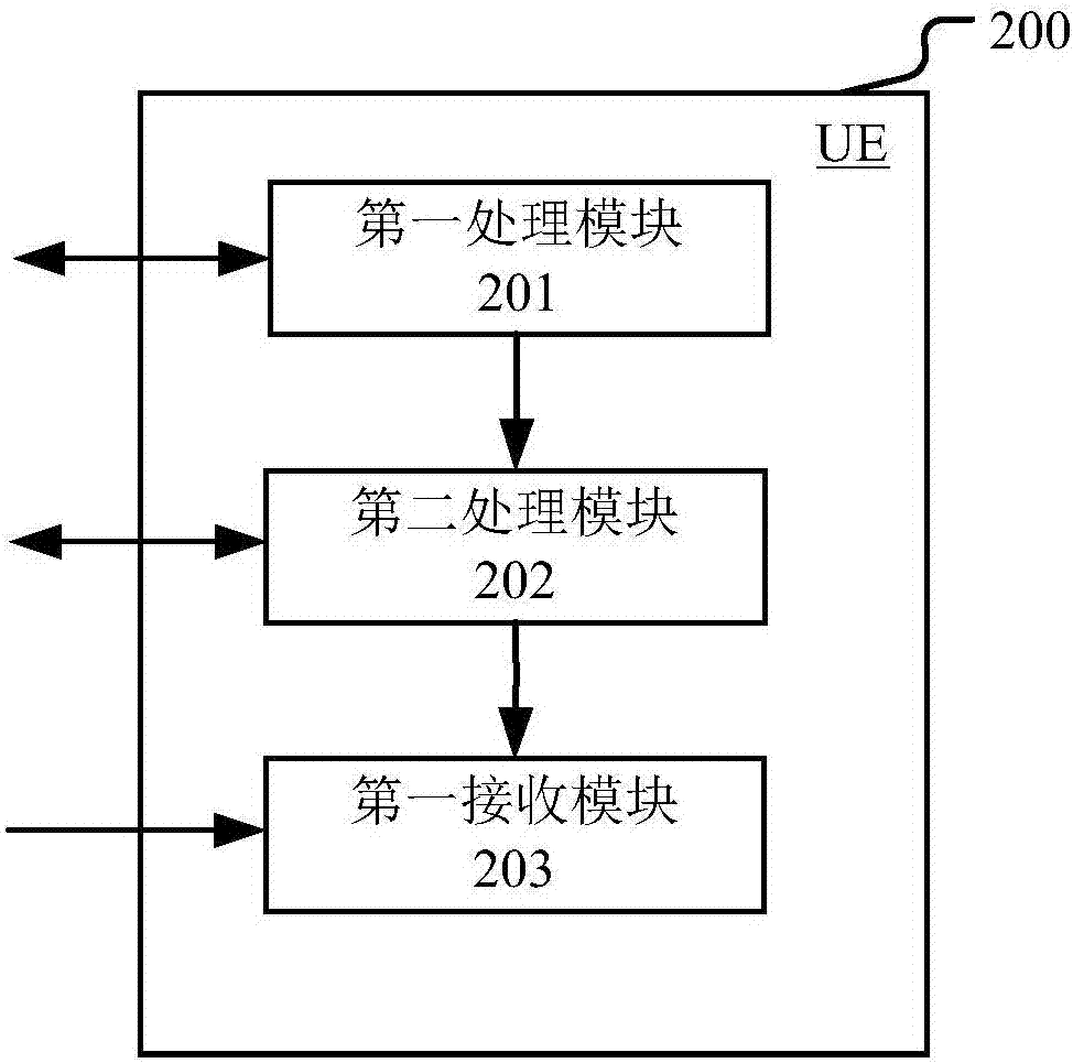
[0235] Embodiment 3 is a structural block diagram of a processing device used in UE, as shown in the attached image 3 shown. attached image 3 Among them, the UE device 200 is mainly composed of a first processing module 201 , a second processing module 202 and a first receiving module 203 .
[0236] The first processing module 201 is used to send the first wireless signal in the first time window; the second processing module 202 is used to send the second wireless signal in the second time window; the first receiving module 203 is used to receive the third wireless signal .
[0237] In Embodiment 3, the first wireless signal includes first information, and the second wireless signal includes second information. The first information and the second information are used to determine M merging vectors. The first information is used to determine M vector groups, and the second information is used to determine M coefficient groups. The M vector groups are in one-to-one corr...
PUM
 Abstract
Description
Claims
Application Information
 - R&D
- Intellectual Property
- Life Sciences
- Materials
- Tech Scout
- Unparalleled Data Quality
- Higher Quality Content
- 60% Fewer Hallucinations
Browse by: Latest US Patents, China's latest patents, Technical Efficacy Thesaurus, Application Domain, Technology Topic, Popular Technical Reports.
© 2025 PatSnap. All rights reserved.Legal|Privacy policy|Modern Slavery Act Transparency Statement|Sitemap|About US| Contact US: help@patsnap.com


