Small-sized LNG supplying system

A gas supply system, small technology, applied in fixed-capacity gas storage tanks, gas/liquid distribution and storage, pressure vessels, etc., can solve problems such as inability to meet actual needs, and achieve the effect of reducing stress concentration

Inactive Publication Date: 2018-01-05
XINXING ENERGY EQUIP
6 Cites 3 Cited by

AI-Extracted Technical Summary

Problems solved by technology

[0003] With the development of my country's economy and the vigorous development of LNG in automobiles and ships as power, or as temporary energy in industry, large LNG storage tanks cannot meet actual needs due to site and space constraints. In addition, for the deve...

Method used

A vacuum port 4 is provided on the top of the outer tank body 1, and this port can be used for vacuum pumping, and can prevent the LNG from being leaked due to the occurrence of LNG in the inner tank body 2 and the outer tank body 1 without a safety discharge device. The cryogenic storage tank exploded.
As shown in Figure 2, the pipeline system of this gas supply system mainly contains gasification pipeline 11, liquid level gauge pipeline 12, overflow pipeline 13, liquid inlet pipeline 14, gas phase pipeline 15 and automatic The pressurization pipeline 16, etc., except that the outlet of the self-pressurization pipeline is at the lower part of the storage tank, the rest of the pipelines are arranged in the top connector assembly 8, which realizes the filling, overflow, self-pressurization, and gas supply of low-temperature liquid LNG. etc. Highly integrated. The pipeline system adopts a bent pipe structure in the tank to prevent stress concentration caused by cold shrinkage and heat expansion. In order to facilitate management and operation, various valves, instruments and safety accessories of the pipeline system are respectively surrounded on the outer surface of the storage tank.
Draw from the bottom of the LNG storage tank from the pressurization line 16, after the liquid natural gas is converted into gaseous boosting, then input to the inner tank body from the LNG storage tank top connector assembly 8 through the booster inlet valve 21, maintain the internal A certain working pressure during the working process of the tank ensures the stability of the output of liquid natural gas.
Fig. 1 is a small-scale LNG gas supply system structural representation, comprises LNG cryogenic storage tank and pipeline system, and LNG cryogenic storage tank is a vertical double-cylinder high-vacuum multi-layer heat-insulating cryogenic tank structure, composed of outer tank body 1 It is composed of 2 sleeves with the inner tank body. The outer tank body 1 is made of low-alloy steel plate, with an inner diameter of φ1850mm and a wall thickness of 8mm. The arc-shaped head at the bottom of the traditional pressure tank is canceled, and the bottom plate 10 directly adopts a flat plate structure to replace the arc-shaped head of the traditional tank body. The leg structure can be directly seated on the ground. For small tanks, it improves the flexibility of the equipment and is easy to move and install. The inner tank body 2 is made of austenitic stainless steel plate, and the Rp1.0 value is additionally inspected according to GB24511. The inner diameter is φ1700mm, the plate thickness is 6mm, and the geometric volume is 5m3. The interlayer of the inner and outer tanks is a vacuum insulation layer, and the sealing vacuum of the storage tank is ≤0.05Pa. In order to ensure the low temperature of the inner tank body, the outer surface of the inner tank body 2 is wrapped with a thermal insulation layer 5 composed of aluminum foil and low-temperature thermal insulation paper, and the aluminum foil and low-temperature thermal insulation paper are wrapped with no less than 20 layers.
In summary, the LNG low-temperature storage tank is small in size and light in weight, and the inner tank body 2 adopts a suspension-mounted structure, which replaces the eight-point support and leg support combination structure or the suspension structure adopted by the large-scale low-temperature tank body in the past. The combined combined structure avoids the openin...

Abstract

The invention provides a small-sized LNG supplying system which comprises a low-temperature storage tank and a pipeline system. The low-temperature storage tank is constituted of an inner tank body and an outer tank body in a sleeving-fit mode, the bottom of the outer tank body is of a slab structure, and the inner tank body is fixed through a composite hoisting structure constituted by a bottom positioning assembly and a top connector assembly. The pipeline system comprises a gasification pipeline, a liquidometer pipeline, an overflow pipeline, a liquid inlet pipeline, a gas phase pipeline and a self-pressurization pipeline; and except for an outlet of the self-pressurization pipeline, other pipelines get in and out of the inner tank body from the top connector assembly. According to thesmall-sized LNG supplying system, the size is small, the weight is low, low-temperature LNG filling, overflow, self-pressurization, supplying and the like are highly integrated, site and space limit is overcome, and hoisting operation is flexible.

Application Domain

Technology Topic

Image

  • Small-sized LNG supplying system
  • Small-sized LNG supplying system
  • Small-sized LNG supplying system

Examples

  • Experimental program(1)

Example Embodiment

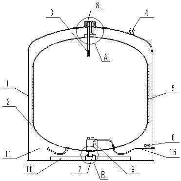
[0023] figure 1 It is a structural diagram of a small LNG gas supply system, including LNG cryogenic storage tanks and pipeline systems. The LNG cryogenic storage tank is a vertical double-cylinder high-vacuum multi-layer thermal insulation cryogenic tank structure, consisting of an outer tank 1 and an inner tank 2 Set composition. The outer tank body 1 is made of low-alloy steel plate, with an inner diameter of φ1850mm and a wall thickness of 8mm. The arc-shaped head at the bottom of the traditional pressure tank is canceled, and the bottom plate 10 directly adopts a flat plate structure to replace the arc-shaped head of the traditional tank body. The leg structure can be directly seated on the ground. For small tanks, it improves the flexibility of the equipment and is easy to move and install. The inner tank body 2 is made of austenitic stainless steel plate, and the Rp1.0 value is additionally inspected according to GB24511. The inner diameter is φ1700mm, the plate thickness is 6mm, and the geometric volume is 5m3. The interlayer of the inner and outer tanks is a vacuum insulation layer, and the sealing vacuum of the storage tank is ≤0.05Pa. In order to ensure the low temperature of the inner tank body, the outer surface of the inner tank body 2 is wrapped with a thermal insulation layer 5 composed of aluminum foil and low-temperature thermal insulation paper, and the aluminum foil and low-temperature thermal insulation paper are wrapped with no less than 20 layers.
[0024] A vacuum port 4 is provided on the top of the outer tank body 1, which can be used for vacuum pumping, and can prevent LNG low-temperature storage tanks from being leaked due to LNG leakage in the inner tank body 2 and the outer tank body 1 has no safety release device. explode.
[0025] To ensure that the storage tank has good thermal insulation performance, an AG molecular sieve low-temperature adsorption device 6 is installed on the inner wall of the lower part of the outer tank body 1 .
[0026] The inner tank body 2 is fixed in the outer tank body by a composite hoisting structure made of a bottom positioning component 7 and a top connector component 8 . like Figure 4 As shown, the bottom positioning assembly 7 includes a bottom fixing member 7-1, a fiberglass sleeve 7-2 and a guide pin 7-3. The bottom fixing part 7-1 is welded to the center of the bottom plate of the outer tank body 1, the guide pin 7-3 is welded to the center of the lower head of the inner tank body 2, the fiberglass casing 7-2 is inserted into the bottom fixing part 7-1, and the guide pin 7-3 Insert in the fiberglass casing 7-2. In this way, the cold shrinkage and thermal expansion of the inner tank body are fully considered, and the axial free movement can be made. At the same time, the glass fiber reinforced plastic sleeve 7-2 greatly reduces the cold energy transmission of the inner and outer tank bodies. like image 3 As shown, the top connector assembly 8 includes a connecting pipe 8-1, a flange 8-2 and a connector 8-3, the flange 8-2 is welded to the top of the head on the inner tank body 2, and the connecting pipe 8-1 is welded to the flange 8-2, and then welded with the connector 8-3, the connector 8-3 is welded with the reinforcing plate 8-4, the reinforcing plate 8-4 is welded and fixed with the outer tank body 1, and the opening of the outer tank body 1 is repaired Strong effect, like this, inner tank body 2 and outer tank body 1 are welded and fixed. The composite hoisting structure ensures the structural stability between the inner tank body and the outer tank body, and eliminates the phenomenon that the inner tank body is broken due to cold shrinkage after the inner tank body is filled with liquefied natural gas. At the same time, the application of the top connector assembly 8 makes the pipe The road is more centralized, avoiding openings on the cylinder and head of the outer tank and inner tank, which is beneficial to reduce the vacuum leakage rate between the inner and outer tanks, maintain the vacuum degree, and improve the overall safety of the LNG cryogenic storage tank.
[0027] To sum up, the LNG low-temperature storage tank is small in size and light in weight. The inner tank body 2 adopts a suspension-mounted structure, which replaces the combination structure of eight-point support and outrigger support or the combination of pulling and hanging used in the past for large-scale low-temperature tanks. The structure avoids the opening of the outer tank body to install supports, reduces leakage points, and ensures the vacuum degree.
[0028] like figure 2 As shown, the pipeline system of this gas supply system mainly includes gasification pipeline 11, liquid level gauge pipeline 12, overflow pipeline 13, liquid inlet pipeline 14, gas phase pipeline 15 and self-pressurization pipeline 16, etc. , except that the outlet of the self-pressurization pipeline is in the lower part of the storage tank, the rest of the pipelines are arranged in the top connector assembly 8, realizing the high integration of cryogenic liquid LNG filling, overflow, self-pressurization, gas supply, etc. The pipeline system adopts a bent pipe structure in the tank to prevent stress concentration caused by cold shrinkage and heat expansion. In order to facilitate management and operation, various valves, instruments and safety accessories of the pipeline system are respectively surrounded on the outer surface of the storage tank.
[0029] The liquid inlet pipeline 14 is the pipeline for filling LNG in the LNG cryogenic storage tank, and is divided into two pipes, both of which enter the inner tank body from the liquid inlet pipe of the top connector assembly 8, and the inner tank body is divided into two paths. like image 3 As shown, the top liquid inlet pipe 14-1 fills LNG from the top of the inner tank, and the bottom liquid inlet pipe 14-2 fills LNG from the top connector assembly 8 along the interlayer of the inner and outer tanks and fills LNG from the bottom of the inner tank. For the top liquid inlet pipe 14-1, in order to prevent the liquid from entering the top of the storage tank, the liquid flowing straight down will have a strong impact on the bottom of the inner tank, which will cause damage to the tank body for a long time. 1 lower end is provided with spray pipe 3.
[0030] The inlet and outlet pipes of the liquid level gauge pipeline 12 are arranged at the top connector assembly 8, and the pipeline includes indicators such as a liquid level gauge 12-1 and a pressure gauge 12-2 to understand the situation of LNG in the inner tank.
[0031] The gasification pipeline 11 is a pipeline for converting liquefied natural gas LNG into gaseous natural gas CNG and providing it to users. The gasification pipeline 11 is provided with an overlapping guide device 9 at the bottom of the inner tank body 2. This structure can ensure the stability of the inner pipeline system, and also consider the allowance for thermal expansion and contraction, and reduce the temperature caused by temperature changes. stress concentration and prevent the pipeline from breaking. The gasification pipeline 11 is led out from the bottom of the inner tank body 2, and a cut-off valve is set in the pipeline, and then connected to the vaporizer 17, and connected to the gas supply interface through the gas supply cut-off valve 18.
[0032] The gas phase pipeline 15 leads out from the top connector assembly 8 , and the lower part is divided into two channels, one channel is connected to the gasification pipeline 11 , and the other channel is connected to the overflow pipeline 13 . When the pressure in the tank exceeds the set pressure of the pressure-reducing valve 19, the pressure-reducing regulating valve 21 opens to lead the gas in the tank to the gasification pipeline 11 through the gas phase pipeline 15, and supply it to the user through the vaporizer 17 and the gas supply interface. When the pressure in the tank drops below the set pressure of the pressure relief valve 19, the pressure relief regulating valve 20 is closed. When the tank is filled with LNG, the gaseous pressure in the inner tank increases, and the gaseous natural gas overflows through the overflow pipeline 13 to ensure the smooth progress of the filling process. In order to ensure safety, all discharge ports of the overflow pipeline 13 adopt centralized Recycled pipe, install flame arrester.
[0033]The booster pipeline 16 is led out from the bottom of the LNG storage tank, after the liquid natural gas is converted into a gaseous booster, it is input into the inner tank body from the connector assembly 8 on the top of the LNG storage tank through the booster inlet valve 21, and the inner tank body is kept working. A certain working pressure in the process ensures the stability of the output of LNG.
[0034] This system is a small gas supply system, and the vacuum pumping device and vacuum measuring device are uniformly arranged on the top of the storage tank for easy operation and detection.
[0035] The inner tank of this gas supply system is small in size and light in weight, and can be fixed by hanging, realizing the high integration of low-temperature liquid LNG filling, overflow, self-pressurization, and gas supply; the small-volume storage tank overcomes the The site and space are limited, and the hoisting and operation are flexible; at the same time, it meets the supporting needs of low-temperature storage and transportation, gas filling stations and other products.

PUM

no PUM

Description & Claims & Application Information

We can also present the details of the Description, Claims and Application information to help users get a comprehensive understanding of the technical details of the patent, such as background art, summary of invention, brief description of drawings, description of embodiments, and other original content. On the other hand, users can also determine the specific scope of protection of the technology through the list of claims; as well as understand the changes in the life cycle of the technology with the presentation of the patent timeline. Login to view more.

Similar technology patents

Cushion plate

InactiveUS20050263367A1Reduce stress concentrationPrevent abrasionFluid actuated brakesFluid actuated clutchesPistonCushion
Owner:NHK SPRING CO LTD +2

Classification and recommendation of technical efficacy words

  • Reduce stress concentration

Flexible heart valve

InactiveUS20050096739A1Reduce stress concentrationHeart valvesProsthesisCommissure
Owner:EDWARDS LIFESCIENCES CORP

Excavating method for jump-digging of double-side wall guide pit combined arch part of tunnel

ActiveCN102182466AReduce stress concentrationReduce surrounding rock disturbanceUnderground chambersTunnel liningSubsidenceStress concentration
Owner:CHINA RAILWAY SHANGHAI DESIGN INST GRP

Valve body and seal assembly

InactiveUS6955181B1Reduce stress concentrationReduce elastomer stressCheck valvesBuilding constructionsEngineeringStress concentration
Owner:S P M FLOW CONTROL
Why Eureka
Try Eureka